-6-
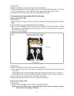
Fig. 5
<<Reassembly>>
Reverse the disassembly procedure. Note the following at reassembly:
(1) When reassembling Terminal Ass'y (E)
[34]
, be sure to mount the jack located internally on the left side
prior to the EB battery box. (The two parts cannot be assembled if mounted in reverse order.)
(2) Be careful to prevent internal wires from being caught between other parts.
3. Disassembly and reassembly of the front housing
Removing the function PCBA
<<Disassembly>>
(1) Remove the three connectors, and then remove the four Machine Screws (W/Flange) M2.6 x 10 (Black)
[19]
.
(2) Use a soldering iron to remove internal wires from the speakers.
(3)
Move Function PCBA
[20]
aside a little, and then remove the Machine Screw (W/Flange) M3 x 10 (Black)
[9]
located near the end of the Rubber Antenna
[1]
. Then you can remove the internal wire connected to
the Rubber Antenna
[1]
. (Fig. 5)
(4) Remove Function PCBA
[20]
.
<<Reassembly>>
Reverse the disassembly procedure. Note the following at reassembly:
(1) When soldering internal wires on the speakers, carefully check the colors of internal wires for proper
connections.
Right speakers (found on the left in disassembled status): Internal wire colors are red (+) and blue (-).
Left speakers (found on the right in disassembled status): Internal wire colors are white (+) and blue (-).
(2) Do not forget to connect the internal wire to the Rubber Antenna
[1]
.
(3) When connecting each connector, be sure to fit it fully into the receptacle.
Removing the Controller PCBA
<<Disassembly>>
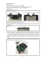
(1) Remove the two Dials
[6]
from the front of the Front Housing Ass’y
[8]
.
NOTE: Wrap a piece of thick cloth around each Dial [6], and then remove it with pliers or another
tool. Be careful not to damage the Dial [6].
Connectors
Soldered positions
Machine Screw (W/Flange) M3 x 10 (Black)
[9]
is located under Function PCBA
[20]
.

