background image

5

English

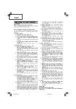
Apply cutting fluid to the tap sufficiently.

First, use preceding tap.

Cut a notch on the shank of a tap so that pawl
of the chuck can be hooked on. (

Fig. 1

)

Only use a tap with a smaller cutting torque (such
as a spiral tap or a spiral-point tap).

HOW TO USE

1. Switch operation

After pulling back the trigger of the switch, depress
the switch stopper. Even after the finger is removed,
the switch will remain ON, proving convenient for
machine continuous operation. To turn OFF the
switch, by merely pulling the trigger again and
releasing it, the switch stopper will be released.

2. Adjusting the number of revolution

This machine incorporates an electronic control
circuit which can adjust the number of tap's
revolution by non-step. Adjust the dial to select the
correct number of revolution, corresponding with
the tap's size, the material to be tapped, and the
working condition. Graduation “1” stands for the
lowest speed; and “5“ for the top speed. (See 

Fig.

3

) When graduation “1“ is selected, there may be

times when the machine will not rotate due to the
power supply conditions.

3. To tap

(1) When the tap is pressed to the hole which is to be

tapped, the floating spindle is pushed into the tapper,
converting the revolution to normal for tapping.
While tapping, press the tap lightly to the hole.

(2) When tapping is completed to the prescribed depth,

pull back the tapper lightly, so that the floating
spindle turns in reverse revolution and the tap comes
off automatically.

4. Power to press the tapper

Tapping cannot be speeded up, even if the tap is
pressed beyond the necessary degree, because
tapping speed is decided by the degree of revolution.
Instead, it will result in breaking the tap or damaging
the tap threads. Therefore, press the tapper lightly
so that the floating spindle is not pushed out.

5. Conform the tap to the prepared hote.

Conform the tap to the prepared hole and insert
it directly in. Inserting it at an angle will exert undue
stress, possible breaking the tap.

6. When tapping a blind hote, follow the procedure

as shown in Fig 4.

(1) Measure the length from the head of the tap

corresponding to the depth of the hole, inserting
the tap into a rubber or vinyl tube leaving exactly
the same length as the tap.

(2) Pull back the tapper when the end of the rubber tube

touches the surface of the material to be tapped,
so that it then can be tapped to exactly the same
depth without breaking the tap.

7. Relationship between thread diameter and prepared

hole

Use the specifications in 

Table 1

 to create the most

suitable prepared hole.

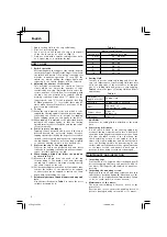
Table 1

Metric coarse thread

Thread dia.

Prepared hole dia.

3 mm

2.5 - 2.6 mm

4

3.3 - 3.4

5

4.2 - 4.3

6

5.0 - 5.1

8

6.8 - 6.9

10

8.5 - 8.6

8. Cutting fluid

In order to get the sharp tap cutting and life of the
tap, it is important to select cutting fluid that best
suits the properties of the material to be tapped.
Use of a cutting fluid will get more easy tapping.

Table 2 

shows the types of cutting fluids and their

applications.

Table 2

Properties of
tapped material

Cutting fluid

Cast iron

Cutting fluid is not used

Steel

Rapeseed oil,
non-waterbased cutting oil

Copper alloys

Light oil,
Spindle oil

Aluminum

Light oil

CAUTION

Make sure no cutting fluid is attached to the main
unit.

9. Concerning drill chucks

A drill chuck is fixed to the floating spindle by
means of the taper attachment. In case a drill chuck
should be disengaged from the unit, remove oil and
dirt from the taper section of the chuck and the
chuck attaching section of the spindle, let three
claws of the chuck withdraw, and mount the chuck
onto the floating spindle by hammering its end
surface with a wooden hammer. Pay special attention
to the taper section and handle it with care to
prevent it from being scratched or damaged.

MAINTENANCE AND INSPECTION

1. Inspecting taps

Continued use of a tap with a dull cutting edge will
decrease tapping efficiency and put extra load on
the motor. Dull taps should replaced as quickly as
possible.

2. Inspecting the mounting screws:

Regularly inspect all mounting screws and ensure
that they are properly tightened. Should any of the
screws be loose, retighten them immediately. Failure
to do so could result in serious hazard.

3. Maintenance of the motor:

The motor unit winding is the very “heart” of the
power tool.
Exercise due care to ensure the winding does not
become damaged and/or wet with oil or water.

01Eng_P20SA2

12/26/08, 9:43

5

Summary of Contents for UT 8V

Page 1: ...er Elektrisches Steuerungssystem Read through carefully and understand these instructions before use Dieses Anleitung vor Benutzung des Werkzeugs sorgfältig durchlesen und verstehen Handling instructions Bedienungsanleitung 001Cover_P20SA2 12 26 08 9 44 1 ...

Page 2: ...Gewindehaken handle can be hooked eingehakt werden kann abschleifen 3 Tap Gewindeschneidstück 4 Drill chuck Bohrfutter 5 Floating Spindle Gleitspindel 6 Dial Skalenscheibe 7 Graduation Abstufung 8 Rubber or vinyl tube Gummi oder Vinyl Schlauch 9 L the depth of tapping L Gewindetiefe L 3 the depth of prepared hole L 3 Tiefe des vorgebohrten Lochs A Wear limit Verschleißgrenze B No of carbon brush N...

Page 3: ...der ernsthaften Verletzungen kommen Only for EU countries Do not dispose of electric tools together with household waste material In observance of European Directive 2002 96 EC on waste electrical and electronic equipment and its implementation in accordance with national law electric tools that have reached the end of their life must be collected separately and returned to an environmentally comp...

Page 4: ...ery pack picking up or carrying the tool Carrying power tools with your finger on the switch or energising power tools that have the switch on invites accidents d Remove any adjusting key or wrench before turning the power tool on A wrench or a key left attached to a rotating part of the power tool may result in personal injury e Do not overreach Keep proper footing and balance at all times This e...

Page 5: ...reasonable load to be applied to the motor possibly damaging the motor In particular be sure to avoid any forceful operation of the machine which will cause the tap to stop midway Make sure to select a correct number of revolution for smooth tapping to be performed Voltage by areas 110V 115V 120V 127V 220V 230V 240V Input 285 W No load speed Forward 60 330 min Reverse 120 660 min Capacities Steel ...

Page 6: ...e tap corresponding to the depth of the hole inserting the tap into a rubber or vinyl tube leaving exactly the same length as the tap 2 Pull back the tapper when the end of the rubber tube touches the surface of the material to be tapped so that it then can be tapped to exactly the same depth without breaking the tap 7 Relationship between thread diameter and prepared hole Use the specifications i...

Page 7: ...cribed in each country must be observed MODIFICATION Hitachi Power Tools are constantly being improved and modified to incorporate the latest technological advancements Accordingly some parts i e code numbers and or design may be changed without prior notice GUARANTEE We guarantee Hitachi Power Tools in accordance with statutory country specific regulation This guarantee does not cover defects or ...

Page 8: ...eiten Benutzen Sie keine Elektrowerkzeuge wenn Sie müde sind oder unter Einfluss von Drogen Alkohol oder Medikamenten stehen Bei der Arbeit mit Elektrowerkzeugen können bereits kurze Phasen der Unaufmerksamkeit zu schweren Verletzungen führen b Benutzen Sie eine persönliche Schutzausrüstung Tragen Sie immer einen Augenschutz Schutzausrüstung wie Staubmaske rutschsichere Sicherheitsschuhe Schutzhel...

Page 9: ...chtung wird schwierig Angewinkeltes Gewindeschneiden ohne Abstimmung mit dem Loch kann zu Gewindebruch führen 4 Gewindeschneider niemals während des Drehens berühren Während der Gewindeschneider dreht keine Körperteile oder Kleidungsstücke mit dem Gewindeschneider oder dem Bohrfutter usw in Kontakt treten lassen um sich keine Schneidwunden zuzuziehen und zu vermeiden daß Fetzen um die Drehteile au...

Page 10: ...inger zurückgenommen wird verbleibt der Schalter in Einstellung ON so daß kontinuierlicher Betrieb möglich ist Zum Ausschalten des Schalters OFF einfach den Auslöseschalter erneut ziehen und loslassen Der Schalterstopper wird dann freigegeben 2 Einstellung der Umdrehungszahl Diese Maschine enthält eine elektronische Steuerschaltung die die Umdrehungszahl stufenlos einstellt Die Drehscheibe so eins...

Page 11: ...nutzte Kohlebürsten führen zu Motorproblemen Deshalb wird eine Kohlebürste durch eine neue ersetzt die dieselbe Nummer trägt wie auf der Abbildung gezeigt wenn sie teilweise oder ganz verbraucht ist Darüber hinaus müssen die Kohlebürsten immer sauber gehalten werden und sie müssen sich in der Halterung frei bewegen können 䡬 Auswechseln Die Bürstenkappe mit einem Schraubenzieher auseinandernehmen D...

Page 12: ...triebslärm und Vibration Die gemessenen Werte wurden entsprechend EN60745 bestimmt und in Übereinstimmung mit ISO 4871 ausgewiesen Gemessener A gewichteter Schallpegel 89 dB A Gemessener A gewichteter Schalldruck 78 dB A Messunsicherheit KpA 3 dB A Gehörschutz tragen Der typische gewogene quadratische Mittelwert der Beschleunigung überschreitet 2 5 m s2 nicht 02Ger_P20SA2 12 26 08 9 44 11 ...

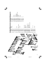
Page 13: ...7C 1 110V 120V 24 25 2 340087D 1 127V 24 25 3 340087E 1 220V 230V 24 25 4 340087F 1 240V 24 25A 340087K 1 230V 24 FRG HOL 26 1 27 961781 2 28 999043 2 29 981586 2 30 983552 1 29 39 31 943452 1 32 943420 1 33 992509 2 D5 45 34 1 957747 1 A B C D 34 2 971667Z 1 FOR FRG 35 959140 3 36A 317491 1 37 930153 1 38 957561 1 39 961681 2 M4 5 40 962994 1 41B 301653 5 D4 20 42 983572 1 43 1 983985 1 100V 127V...

Page 14: ...13 03Back_P20SA2 12 26 08 9 44 13 ...

Page 15: ...ame and Address 5 Dealer Name and Address Please stamp dealer name and address Deutsch GARANTIESCHEIN 1 Modell Nr 2 Serien Nr 3 Kaufdaturn 4 Name und Anschrift des Kunden 5 Name und Anschrift des Händlers Bitte mit Namen und Anschrift des Handlers abstempeln 03Back_P20SA2 12 26 08 9 44 14 ...

Page 16: ...15 1 2 3 4 5 03Back_P20SA2 12 26 08 9 44 15 ...

Page 17: ...16 03Back_P20SA2 12 26 08 9 44 16 ...

Page 18: ...17 03Back_P20SA2 12 26 08 9 44 17 ...

Page 19: ...h 1 F R Germany Tel 49 2154 49930 Fax 49 2154 499350 URL http www hitachi powertools de Hitachi Power Tools Österreich GmbH Str 7 Objekt 58 A6 Industriezentrum NÖ Süd 2355 Wiener Neudorf Austria Tel 43 2236 64673 5 Fax 43 2236 63373 03Back_P20SA2 12 26 08 9 44 18 ...

Page 20: ...wortung daß dieses Produkt den Standards oder standardisierten Dokumenten EN60745 EN55014 und EN61000 in Übereinstimmung mit den Direktiven des Europarats 2004 108 CE und 98 37 CE entspricht Diese Erklärung gilt für Produkte die die CE Markierung tragen English EC DECLARATION OF CONFORMITY We declare under our sole responsibility that this product is in conformity with standards or standardized do...

Reviews: