background image

Chapter 9. Environment Setup 

9-10 

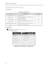
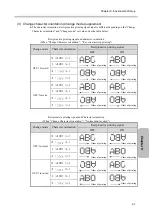
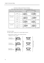
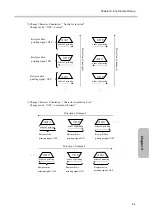
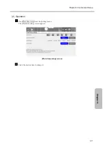
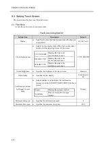
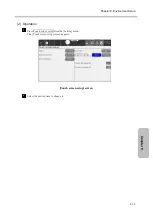
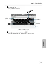
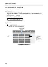
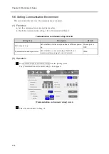
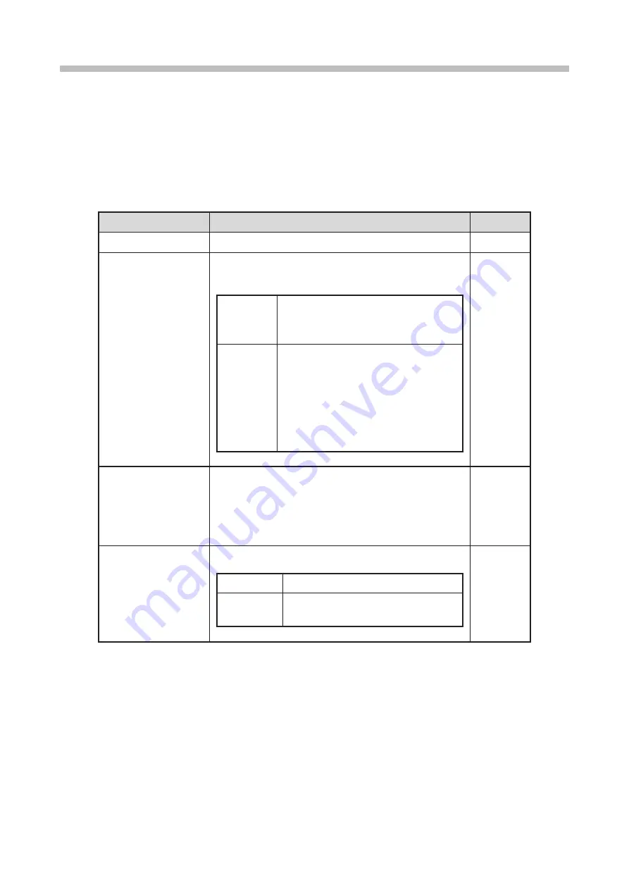
9.2. Setting Date and Time 

This section describes how to set the date and time. 


(1)  Functions 

●  Sets the date and time values. 


Date/time setup item list 

Setting item 

Description 

Default 

Current time 


Sets the current date and time (clock function). 

– 

Calendar time control 


Selects whether to use or stop using the current date 

and time as the calendar time. 


same as 

current time 


Sets the time displayed in the clock 

at the upper-right corner of the 

screen as the calendar time. 

clock stop 


Sets a specified time as the calendar 

time. 


The clock (current time) at the 

upper-right corner of the screen is 

not stopped. 


The value must be no later than the 

current date and time. 


same as 

current time 

Calendar time 


Sets the calendar time. 


The print description of calendar characters is based 

on [Calendar time] instead of [Current time]. 


This can be set only when [Calendar time control] is 

[clock stop]. 

– 

Clock system


Sets the 24-hour clock or 12-hour clock. 


24-hour clock  00.00 to 23:59 

12-hour clock 

A.M. 00:00 to 11:59 

P.M. 00.00 to 11:59 


24-hour 

clock 

[Note] 

When the substitution rule is set to the "year", do not select [clock stop] and set a year earlier 
than the current year. Otherwise, the "year" is replaced by a space.


Summary of Contents for UX2 Series

Page 1: ...HITACHI Printer Model UX2 Instruction Manual Before using the printer thoroughly read this instruction manual for optimum printer use After reading the manual properly keep it for future reference ...

Page 2: ...ions and follow the necessary procedures If you have any questions contact your Hitachi sales representative January 2022 rev A No part of this manual may be copied or reproduced without permission The contents of this manual are subject to change without notice for improvement All Right Reserved Copyright 2021 Hitachi Industrial Equipment Systems Co Ltd ...

Page 3: ... product or system including the product cannot be used in countries or areas other than those which have concluded a sales contract Disclaimer Do not perform operation not in accordance with this instruction manual such as using replacement parts other than ones supplied by Hitachi or modifying parts Doing so may cause machine failure or personal injury Hitachi will not bear any responsibility fo...

Page 4: ...ks from outside Malfunction harm and damage due to program and or data tampering from outside Used as a step for attacking other systems However the security level required in control systems varies depending on the system In addition potential security risks are not consistent but change on a daily basis Not only in Hitachi products but also in system components the security protection support fu...

Page 5: ...ic prior written permission THIS SOFTWARE IS PROVIDED BY THE COPYRIGHT HOLDERS AND CONTRIBUTORS AS IS AND ANY EXPRESS OR IMPLIED WARRANTIES INCLUDING BUT NOT LIMITED TO THE IMPLIED WARRANTIES OF MERCHANTABILITY AND FITNESS FOR A PARTICULAR PURPOSE ARE DISCLAIMED IN NO EVENT SHALL THE COPYRIGHT OWNER OR CONTRIBUTORS BE LIABLE FOR ANY DIRECT INDIRECT INCIDENTAL SPECIAL EXEMPLARY OR CONSEQUENTIAL DAM...

Page 6: ......

Page 7: ...ng those related to potential warnings to be observed Detailed information is furnished by a picture within the symbol outline a shock hazard is indicated by the example shown at left The symbols are used to describe prohibited actions The details of a prohibited action are given by a picture within or near the symbol outline the example shown at left dictates that you must keep flames away The sy...

Page 8: ... managed under the Industrial Safety and Health Act NOTE If extraneous noise enters the product it may malfunction or break down For maximum noise immunity observe the following installation and wiring precautions Ensure that 100 or 200 VAC power cables are not bundled with other power supply cables Insulate the product main body and print head so that they do not come into direct contact with the...

Page 9: ...lly conductive beaker and connect the beaker securely to the ground Do not let the tip of the printing head enter the beaker Ink particles used for printing are electrically charged An ungrounded beaker has a gradually rising charge possibly catching on or causing a fire WARNING Use an AC power cable within the following range When using an inlet 100 to 240 VAC When using a power receiving termina...

Page 10: ...make sure that no makeup has entered and no vapors remain inside CAUTION When cleaning the product or replenishing ink or makeup wear protective gloves and safety goggles to avoid direct skin contact If the ink or makeup comes into contact with skin wash thoroughly with soap and warm or cold water When transferring the ink or makeup to or from a bottle exercise caution to prevent it from coming in...

Page 11: ...ly flush with warm or cold water and consult a physician Before servicing the product be sure to stop the ink ejection This is because ink or makeup may splash into your eyes or mouth or onto your hands or clothing If any ink or makeup enters your eyes or mouth immediately flush with warm or cold water and consult a physician If an earthquake fire or other emergency occurs while the printer is eng...

Page 12: ...s device must accept any interference received including interference that may cause undesired operation This equipment has been tested and found to comply with the limits for a Class A digital device pursuant to part 15 of the FCC Rules These limits are designed to provide reasonable protection against harmful interference when the equipment is operated in a commercial environment This equipment ...

Page 13: ... each ink for details AVERTISSEMENT Tenir hors de portée du feu L encre et la composition sont inflammables Tenir la machine hors de portée du feu Nettoyez et séchez immédiatement les projections d encre et de composition Soyez prudent lorsque vous manipulez l encre la composition Le stockage doit respecter les obligations réglementaires locales Lisez attentivement la fiche signalétique de sécurit...

Page 14: ......

Page 15: ...ential that you read this manual thoroughly to gain a complete understanding of the printer and use it correctly After reading the instruction manual properly keep it for future reference Scope of application This instruction manual is prepared for all the models of HITACHI IJ Printer Model UX2 for Dye Ink which are listed in the table below Please be advised that the differences among these model...

Page 16: ...he cause of a unit fault Communication Manual The communication manual describes how to control the unit through communication It contains a communication connection method a list of communication codes and countermeasures for warnings and faults in communication It is recommended to use this manual in combination with the instruction manual and the basic operation manual Handling guidance of each...

Page 17: ...iii ...

Page 18: ...r describes the procedures to create messages to be printed with the Hitachi IJ Printer Chapter 6 Character Print This chapter describes the information about character printing with the Hitachi IJ Printer Chapter 7 Auxiliary Functions This chapter describes the functions to manage messages created with the Hitachi IJ Printer Chapter 8 Ink and Makeup Replenishment This chapter describes the proced...

Page 19: ...layed when a warning or fault occurs in the Hitachi IJ Printer and how to check the occurrence status and handle the warning or fault Chapter 13 Troubleshooting Guide This chapter describes points to be checked when the Hitachi IJ Printer does not start up normally Chapter 14 Emergency Procedures This chapter describes actions to be taken if an emergency such as an earthquake or fire occurs ...

Page 20: ... Ink Concentration Control 1 10 1 2 8 Gutter Cleaning 1 11 1 2 9 Protection Sheet 1 12 2 Specifications 2 1 3 Component Names and Functions 3 1 3 1 External Views 3 2 3 2 Unit Internal Parts Arrangement 3 6 3 3 Print Head 3 7 3 4 Safe Clean Station Optional parts 3 8 3 5 Screen Display 3 9 4 Basic Operation 4 1 4 1 Basic Operation Flow 4 2 4 1 1 Operating Scheme 4 2 4 1 2 Status 4 3 4 1 3 Operatio...

Page 21: ... be Edited 5 12 5 5 2 Setting Number of Print Lines 5 13 5 5 3 Deleting Inserting and Adding Print Items 5 14 5 5 4 Setting Dot Matrix Inter character Space and Other Parameters 5 16 5 5 5 Printing Barcode 5 22 5 6 Setting Print Specifications 5 27 5 6 1 Setting Character Height Character Width and Character Orientation 5 27 5 6 2 Setting Repeat Print 5 34 6 Character Print 6 1 6 1 Printing Charac...

Page 22: ...ing Pattern 7 23 7 3 4 Creating User Pattern of Free Size 7 26 7 3 5 Calling Bitmap BMP File 7 28 7 4 Back Up Data to USB Memory 7 30 7 4 1 Copying data at once 7 30 7 4 2 Copy data individually 7 37 7 5 Editing Pattern of Standard Character 7 42 7 6 Editing Substitution Rules 7 44 7 7 Switching Display Language 7 46 7 8 Changing Layout of HOME Screen 7 47 8 Ink and Makeup Replenishment 8 1 8 1 Re...

Page 23: ...Using Head Cleaning Station 11 5 11 3 Starting Operation Using Cleaning station 11 14 12 When Fault or Warning Occurs 12 1 12 1 Display When Fault or Warning Occurs 12 2 12 2 On screen Message Descriptions 12 5 12 2 1 Fault Messages 12 5 12 2 2 Warning Messages 12 10 12 2 3 Other Messages 12 12 12 2 4 Yellow Ink Specific Messages 12 12 12 3 Checking Fault and Warning Occurrence Status 12 13 12 4 A...

Page 24: ......

Page 25: ...1 1 Chapter 1 Chapter 1 1 Overview 1 1 Purpose and Function Description 1 2 Usage Precautions Chapter 1 Chapter 3 Chapter 4 Chapter 5 Chapter 2 ...

Page 26: ...hment system While the unit is in operation the ink reservoir automatically supplies the ink and the makeup reservoir automatically supplies the makeup to the ink main tank at regular intervals If the ink or makeup replenisher level is too low an alarm is issued In this case replace the cartridge and replenish the ink or makeup immediately For the replenishment procedures see Chapter 8 Makeup serv...

Page 27: ...leaning bottle before setting the makeup cartridge bottle Tighten the cap of the makeup cartridge bottle after use Turn it upside down to check if there is no leakage of makeup If the makeup in the makeup cartridge bottle is used as a cleaning solution the volume of makeup in the makeup cartridge bottle decreases When it is set in the unit please use a makeup cartridge bottle that contains makeup ...

Page 28: ...t with makeup When restarting operation after storage drain the makeup from inside the unit and fill the unit with ink See the Technical Manual 5 15 Long term Shutdown for details Note that since long term shutdown storage requires special work it is recommended to contact your nearest local distributor and ask for the work Recommended shutdown period Storage temperature Recommended shutdown perio...

Page 29: ... or the distance between the print material and the print head is short ink splashes may stain the end of the print head and the print head cover If this condition is left unresolved the staining will be worse resulting in a print error or emergency stop If a print error or emergency stop frequently occurs due to staining caused by ink splashes stop the operation in progress and clean the end of t...

Page 30: ... on the HOME screen see 5 1 HOME Screen Initial Screen The no cleaning stop procedure is valid even while the startup sequence is being executed Shutdown is inactive during the startup sequence Note You can use Shutdown to stop operation up to twice in a row When operation is stopped using No cleaning stop if it is left in that state the ink will become stuck in the nozzle and cause ink stream ben...

Page 31: ...Chapter 1 Overview 1 7 Chapter 1 Press No cleaning stop in the Shutdown Process Confirmation message Shutdown Process Confirmation screen 2 Press No cleaning stop ...

Page 32: ...more once it is started in the ink ejection state During the operation the ink viscosity is adjusted automatically and returns to the initial value The required operation time varies depending on the ambient temperature or ink types used See the handling guidance of each ink for details 2 Cautions when daily operating time is relatively long This unit emits ink during printing so the outside and i...

Page 33: ...Heating Unit Temperature Sensor Fault or Ink Heating Unit Over Current is displayed putting the printer in the fault stop You can restart the printer by pressing Reset or Close However the ink will be set not to be heated even if the temperature drops thereafter b Once the unit is set not to heat the ink the following message is always displayed when the power is turned on thereafter Press Close t...

Page 34: ...e unit will enter the fault stop state You can restart the unit by pressing Close However the setting will be changed not to control ink concentration based on the measurement result using the viscometer thereafter Once the setting of automatic concentration control is canceled the following message will always appear at power on Press Close to cancel the message and contact your nearest local dis...

Page 35: ... time without the gutter being cleaned these components will gradually accumulate in the gutter This together with the ink coming into contact with it may cause an error stemming from a dirty head If this fault occurs perform the following actions 1 and 2 1 Clean the gutter and its perimeters with makeup periodically 2 See the procedures described in the Technical Manual 5 6 Cleaning the Gutter to...

Page 36: ...ection sheet after the panel surface is dried b Peel off the removable paper from the back of the protection sheet Do not touch the double sided tape on the back of the protection sheet c Put the protection sheet on the unit screen display as shown in the figure Protection sheet placement 2 Usage precautions Be careful not to get ink or makeup on the protection sheet If ink or makeup is attached t...

Page 37: ...2 1 Chapter 2 2 Specifications Chapter 1 Chapter 2 Chapter 3 Chapter 4 Chapter 5 ...

Page 38: ...ters x 4 line 5 lines 48 characters x 5 lines Upgrade option 200 characters x 5 line 6 lines 40 characters x 6 lines Upgrade option 166 characters x 6 line Font size Horizontal x Vertical line number Standard printhead Maximum vertical dots 48 dots 4x5 1 to 6 lines 5x5 1 to 6 lines 5x8 or 5x7 1 to 4 lines 9x8 or 9x7 1 to 4 lines 7x10 1 to 3 lines 11x11 1 to 2 lines 10x12 1 to 2 lines 12x16 1 to 2 ...

Page 39: ...Rotary encoder pulse Remote control Reciprocative print Output Print ready Fault Warning Print in progress Print complete Online output Ink Makeup Cartridge type Ink viscosity control Alarm function Operation support function Status indicator Animation guidance Password function Maintenance function Operating time control Circulation control Auto cleaning for nozzle and gutter line History of alar...

Page 40: ...Chapter 2 Specifications 2 4 1 A USB to RS 232C conversion cable is required 2 The operating temperature limit differs depending on the ink types See the handling guidance of each ink for details ...

Page 41: ......

Page 42: ...This page is blank ...

Page 43: ...r 3 3 Component Names and Functions 3 1 External Views 3 2 Unit Internal Parts Arrangement 3 3 Print Head 3 4 Safe Clean Station Optional parts 3 5 Screen Display Chapter 1 Chapter 2 Chapter 3 Chapter 4 Chapter 5 ...

Page 44: ...s unit Main power switch Turns the unit ON and OFF Maintenance cover Opened closed for ink and makeup replacement and other maintenance purposes ON STOP switch Turning ON or stops the unit with the main power on Print head Performs printing Maintenance cover knob USB cover Opened closed when copying print data to USB memory Operating status indicator lamps Displays Ready Fault and Warning RFID rea...

Page 45: ...Chapter 3 Component Names and Functions 3 3 Chapter 3 Safe Clean Station Optional parts Unit external view front side Cleaning Station ...

Page 46: ... body is not easily rusted but it may be affected by the environment or cause rust if the unit is left for a long time To prevent rust from forming it is recommended that the surface of the main body be kept as clean as possible Signal connection ports Filter cover Air purge connection port Exhaust duct connection port ...

Page 47: ...Chapter 3 Component Names and Functions 3 5 Chapter 3 Safe Clean Station Optional parts Unit external view rear side Cable of Cleaning Station ...

Page 48: ...bottle and the makeup cartridge bottle are optional parts Unit internal structure Appearance with inner cover removed Unit internal structure with inner cover removed Inner cover Makeup cartridge bottle 1 Ink cartridge bottle 1 Makeup reservoir Ink reservoir Lever handle Lever handle Pressure adjusting screw Ink filter Recovery filter Main ink tank ...

Page 49: ...tructure of the print head inside the dotted box in the figure above is as follows Print head structure Head cover lock screw Loosen to remove the print head cover Print head cover Pull out Pull out The ends of the print head cover and the gutter are different from those of the standard model Ink ejection port Charge electrode Nozzle orifice Plus deflection electrode Gutter Minus deflection electr...

Page 50: ...t head cover temporarily It is available on both left and right sides Print head cable hanger The print head cable can be hooked on it Cleaning Solvent Container Bottle that collects the liquid after cleaning Print head inlet An inlet for inserting the printhead to be cleaned Cleaning Umbilical cable Contains wiring and piping from the printer Tube length 4 5 m Slide block Used to mount the Cleani...

Page 51: ...ch screen use only fingers If the touch panel is operated with a metal or sharp object such as a ballpoint pen it may malfunction or break down 1 HOME screen initial screen For details on the screen see 5 1 HOME Screen Initial Screen For the menu operation see 4 1 3 Operation of Screen Transition Status Current date and time Warn Offline Online HOME screen Menu ...

Page 52: ...and Functions 3 10 2 Message For details on messages see Chapter 12 When Warning or Fault Occurs Main Ink Tank Too Full warning screen Message name Message type Animation display Message No Detail cause and solution Button Close ...

Page 53: ......

Page 54: ...This page is blank ...

Page 55: ...4 1 Chapter 4 4 Basic Operation 4 1 Basic Operation Flow 4 2 Start Operation 4 3 Shutdown Operation Chapter 1 Chapter 2 Chapter 3 Chapter 4 Chapter 5 ...

Page 56: ...es to start and stop operation 4 1 Basic Operation Flow This section describes the basic operations of the unit 4 1 1 Operating Scheme IJ Printer operating scheme Eject ink and Ink stop can be operated on the HOME screen HOME print description Edit Power OFF Power ON Select message Save message Setting ...

Page 57: ...preparing for operation 5 Ink heating The unit is starting up with the ink being heated 6 Stopping The unit is performing the internal process to stop 7 Drop adjust The unit is in the standby state with ink particles not properly charged 8 Cover open The unit is in the standby state with the print head cover open 9 Service The unit is in the circulation control state for maintenance task execution...

Page 58: ...tion 4 4 2 If there is an alarm that has not been reset the display color of Warn is changed When you press Warn the warning list appears Ink Low Warning screen Warning list Press Ink Low Warning Press Warn Ink low warning ...

Page 59: ...s the cartridge Displays the print layout and operating information 5 1 Edit Edits messages 5 2 Select message Calls and prints saved messages 5 3 Save message Saves created messages 5 5 Setting Select the operation status environment setup maintenance etc Chapters 9 and 10 2 Screen transition procedure HOME print description screen is displayed HOME print description screen 1 The items that allow...

Page 60: ...Chapter 4 Basic Operation 4 6 Press Edit The print description edit screen is now displayed Print description edit screen 2 ...

Page 61: ...ing values How to change setting values 1 Inputting values Values are displayed on the screen Open the numeric key window by pressing the value and input a new value 2 Selecting values Setting values are displayed on the screen Open the selection window by pressing the setting value and select one of the choices 2 Operation The detailed setting screen that is displayed by selecting Edit is used as...

Page 62: ...en the numeric key window by pressing the value and input a new value Character height value input screen b Selecting a value for setting item e g Target sensor filter Closes the numerical key window and reverts the value to the original Sets the maximum value Selecting a value for setting item ...

Page 63: ...e previous screen When Back is pressed new settings are canceled and the display returns to the previous screen 2 Screens with Back When Back is pressed the display returns to the previous screen When OK is pressed an edited message to be printed or new settings configured on the User environment setup screen are applied for printing When HOME is pressed new settings are confirmed and the display ...

Page 64: ...Chapter 4 Basic Operation 4 10 b Screen with Back Example of the Save message screen Example of Save message screen Back Save HOME ...

Page 65: ...e If the system shuts down turn off the main power switch To turn on the power again and reuse the system see Chapter 14 Emergency Procedures Remove the print head cover and check whether or not the print head cover and nozzle periphery are soiled by ink Print head cover and nozzle periphery checking for stain Since this unit prints by ejecting ink against the print material the outside and inside...

Page 66: ... the ON switch for about two seconds to turn on the power To turn on the power again ensure that the operating status indicator lamps are off 2 Operating status indicator Operating status indicator lamps Displays Ready Fault and Warning Main power switch Turns the unit ON and OFF ON STOP switch Starts or stops the unit with the main power on If the unit was stopped last time only by the STOP switc...

Page 67: ...rs Select any user Press the user name user The password input window appears Input the password for the user name user and press Enter The HOME screen appears A The saved user names are displayed An icon showing a binder represents a user with administrator rights An icon showing no binder represents a general user B Input the password for the user name user C ...

Page 68: ...nt head to be ready for ink ejection Immediately after ink ejection a little amount of ink may spurt out and soil the surroundings Press Startup at the bottom right of the HOME screen You cannot eject ink when the print head is inserted into the Cleaning station 3 Print head Wiping paper etc Press Ready Press Startup ...

Page 69: ...ecovered from the gutter In this case stop the operation using the following no cleaning stop procedure No cleaning stop procedure Press Shutdown at the bottom right of the HOME screen This no cleaning stop procedure is possible even while the startup sequence is being executed If you stop the unit with this procedure restart the operation according to 4 2 2 When Error Occurs at Start of Operation...

Page 70: ...essure by turning the pressure adjusting screw with a flat screwdriver so that the difference falls within 0 002 MPa of the standard value Input the print target detection signal and check whether or not the printing state and print description are correct If the print target detection signal is input when the status is Ready the set print description is printed 4 Ink pressure display value The va...

Page 71: ...ean inside the area to be cleaned with makeup Clean the nozzle orifice charge electrode deflection electrode and gutter with makeup Also see 3 3 Print Head Cleaning Wipe the makeup on the surface of each part including the mounting base thoroughly with wiping paper and dry the part 1 2 Pull out Print head cover Head cover lock screw Loosen to remove the print head cover 3 Charge electrode Deflecti...

Page 72: ... the end of the print head in the beaker to be ready for ink ejection Press Startup at the bottom right of the HOME screen Cannot eject ink when the print head is inserted into the Print head inlet of the Cleaning station Optional parts 4 Press Eject ink Press Startup ...

Page 73: ...aning stop to stop the ink ejection Also take action in accordance with the Technical Manual 5 4 How to correct ink stream bending and nozzle clogging Install the print head cover and put the unit in the Ready state If the screen status does not change from Cover open to Standby the print head cover may not be appropriately installed Install the print head cover again See 3 1 3 2 Switching from St...

Page 74: ...state and standby state 1 Ready state Standby state switching When the conveyor interlock is activated by the Ready output signal if the status is changed to Standby the conveyor will stop Press Ready at the top of the screen and the Print Abort Confirmation message appears Then press OK Print Abort Confirmation screen 1 Press Ready Press OK ...

Page 75: ...sic Operation 4 21 Chapter 4 2 Standby state Ready state switching Press Standby at the top of the screen and the Print Confirmation message appears Then press OK Print Confirmation screen 1 Press Standby Press OK ...

Page 76: ...g in advance Different password protection can be set for each user A user name can contain up to 12 characters Set whether or not to select a user to be logged in at power on See the Technical Manual 3 3 Selecting login user when power is turned on 2 Operation The administrator sets beforehand to ask the user to log in at power on Turn on the power The Select login user screen appears This icon i...

Page 77: ...23 Chapter 4 Press the user name user The password input window appears User password input screen Input the password for the user name user and press Enter The initial screen appears 2 Input the password for the user name user 3 ...

Page 78: ...e performed automatically Positions of operating status indicator lamps and each switch The power is turned OFF by the STOP switch when ink is being ejected or stopped The main power switch does not have to be turned off Power consumption does not change even if the main power switch remains ON Operating status indicator lamps Displays Ready Fault and Warning Main power switch Turns the unit ON an...

Page 79: ...rocedure to stop ink ejection Press Shutdown at the bottom right of the HOME screen Stops ink ejection with cleaning the circulation route This button does not turn off the power Turns OFF the power automatically after ink jet is stopped like the STOP switch Press Shutdown Stops ink ejection without cleaning the circulation route Not recommended ...

Page 80: ...g the unit by the STOP switch Turn ON the main power switch and press the ON switch for about two seconds to turn on the power When turning OFF the main power switch without using the STOP switch Turn ON the main power switch to turn on the power The nozzle rubber seal prevents the nozzle orifice from being dried and dust from attaching to the plate When the unit will not be used for several days ...

Page 81: ...when the unit is frequently used in a high temperature environment or before the weekend such as a 2 3 day shutdown period This careful cleaning uses a larger amount of makeup than normal cleaning Please note that this function uses makeup approximately double the normal cleaning resulting in lower ink concentration 2 How to use this function Contact your nearest distributor to use this function ...

Page 82: ......

Page 83: ...Screen Initial Screen 5 2 Editing Messages to be Printed Message Edit Screen 5 3 Calling and Printing Saved Messages 5 4 Saving Created Messages 5 5 Setting Print Format Fixed Layout 5 6 Setting Print Specifications Chapter 1 Chapter 2 Chapter 3 Chapter 4 Chapter 5 ...

Page 84: ...hutdown Starts stops the unit 4 2 4 3 Operating information Displays the ink pressure and filter replacement time To select operating information to be displayed set it on the Widget edit screen 10 2 Cartridge replacement Replaces the cartridge 8 1 8 2 HOME screen initial screen Displays the message name Press a menu icon to execute the corresponding function Swipe to scroll the print description ...

Page 85: ...pe Feature Current message The message currently being printed is called a current message When the power is turned on the unit holds the last current message The print layout of the current message is displayed on the HOME screen You can change the contents of the current message by calling one from the saved messages Saved message Multiple messages can be saved with message names ...

Page 86: ...ode of the message name list display on the Select message screen shows the type of print format Style types meaning feature Type Meaning Feature INDIV Individual setup of the fixed layout Multiple dot matrix patterns can be selected Individual setting Print items are stacked from the bottom A B C D E F G XY 2022 01 01 Columns of different formats can be input Columns vertical list with the same l...

Page 87: ... Print Messages 5 5 Chapter 5 2 Operation The HOME screen appears Press the Edit button on the HOME screen HOME screen position of message edit button The message edit screen appears Message edit screen editing current message 1 1 2 ふ ...

Page 88: ...longing to the selected group are displayed When 0 All message names is selected the message names in all groups are displayed Prev Next Switches the message name list display screen Page move Specifies the message name list page Sort Switches the sort order by pressing the header part of the message name list Search condition Input the first several characters of a message name to display only th...

Page 89: ... Select message from the menu The Select message screen appears Select message screen Press display and Display switching and then displays the following screen Appeared the window after pressing display Thumbnail list screen 1 Current message name Prev Next Group No 2 Sort 2 Sort ...

Page 90: ...e desired message name is displayed Select the message name The Select Message Confirmation message appears The print image can be checked in the preview Select Message Confirmation message screen Press on the Select Message Confirmation message screen The selected message is called and the display returns to the HOME screen 3 4 5 5 ...

Page 91: ...signed Messages can be saved to a selected group In Ready state you cannot save created messages If the number of input characters is small the capacity required to save messages decreases Many messages can be saved if each size is small If there are many large messages the number of messages that can be saved is smaller Maximum number of messages to be saved Maximum save count Remarks 300 Upgrade...

Page 92: ...on Press Save message on the HOME screen The Save message screen appears Save message screen Select the message name The keyboard appears For details on the keyboard see 6 1 1 Printing Fixed Characters Screen for selecting message name 1 1 2 Select the message name ...

Page 93: ...tting of Print Messages 5 11 Chapter 5 Input the message name and press Enter Screen for inputting message name Press the save button The message is saved to the specified number Save message screen 3 Input the message name 4 4 ...

Page 94: ...t Items to be Edited There are two methods of selecting the print item to be edited Selecting the print item by directly touching Selecting the print item by or at the right of the screen Screen for specifying target print item You can also change the editing target by directly touching a print item The colored print item is the editing target Change the target print item ...

Page 95: ...r of print lines Functions Sets the number of lines of the selected column The number of lines that can be set is 1 to 6 Maximum number of lines by model type Model type Maximum line count UX2 D 6 Press and Screen for setting number of print lines appears Screen for setting number of print lines The colored print item is the editing target ...

Page 96: ...tes inserts and adds print items for each column Methods of deleting inserting and adding print items Type Operation description Delete col Deletes all the print items in the editing target column Insert col Adds a column before the editing target column Add col Adds a column at the end Screen for deleting inserting or adding print items The colored column is the editing target Add col ...

Page 97: ...Chapter 5 Creation and Setting of Print Messages 5 15 Chapter 5 Modifying columns Delete col Insert col Add col ...

Page 98: ...r character space bold font and barcode Screen for setting dot matrix inter character space etc 1 Bold Sets the character to bold The available bold levels are 1 to 9 2 Line spacing Adjusts the spacing with the line above This is set for each column The available line spacing are 0 to 4 5 or 6 lines 0 to 2 The colored print item is the editing target 4 Inter character space 3 Dot matrix 1 Bold 2 L...

Page 99: ...nd 9 x 7 However for special characters accent characters Russian characters Arabic numbers and Arabic letters select a dot matrix of vertical eight dots since the pattern is designed with vertical eight dots The character types that can be input are defined for each dot matrix A space is entered when there is no character corresponding to the changed dot matrix Character types that can be input b...

Page 100: ... 18 Limitation of total number of vertical dots Model type UX2 D Total number of vertical dots 48 Dot matrix patterns of eight or fewer vertical dots are calculated as eight dots Chimney characters consist of characters which can be written vertically ...

Page 101: ...e designed in inter character space areas Set an inter character space of a value shown in the table below Inter character space setting values Character type 5x5 5 x 8 5x7 9x8 9x7 7x 10 11x 11 10x 12 12x 16 18x 24 24x 32 30x 40 36x 48 Chinese Character 0 4 6 Kana 0 0 2 4 6 Special character 1 1 Alphabet A Alphabet B Inter character space Vertical 8 dots Horizontal 5 dots Dot matrix 5 x 8 Inter ch...

Page 102: ...o be set 4 x 5 4 4 28 5 x 5 5 3 27 5 x 8 5 x 7 5 3 27 9 x 8 9 x 7 9 7 23 7 x 10 7 1 25 11 x 11 11 5 21 10 x 12 10 6 22 12 x 16 12 4 20 18 x 24 18 6 14 24 x 32 24 8 8 30 x 40 30 10 18 36 x 48 36 12 12 5 x 3 chimney 5 0 27 5 x 5 chimney 5 0 27 7 x 5 chimney 7 0 25 If high speed print mode is D1 it is better to select same Inter character space setting for keeping better print quality For details see...

Page 103: ...d End input the setting value in Inter char space check the print description and press OK Screen for inter character space adjustment When the inter character space on the Print format screen is changed the value set in units of characters is changed to the same value The display value of the inter character space on the Print format screen indicates the inter character space of the first charact...

Page 104: ...gits ITF ITF 00 to 99 Maximum 128 digits Enter in 2 digit units NW 7 NW 7 0 to 9 minus period colon Maximum 128 digits EAN 13 EAN 13 0 to 9 EAN 13 Add On 5 EAN 13 Add On 5 0 to 9 EAN 8 EAN 8 0 to 9 UPC A UPC A 0 to 9 UPC E UPC E 0 to 9 Code 128 Code128 Code Set B 0 to 9 A to Z a to z Space FNC1 Code B Code C Symbol Maximum 128 digits Code 128 Code128 Code Set C 0 to 9 FNC1 Code B Code C Maximum 12...

Page 105: ...de set C of code 128 was set when the English alphabet is set for the count upper limit the relevant character is deleted Since start and stop codes are automatically generated input as print description is unnecessary When DM 16 16 or QR 21 21 is selected and when Bold is set to 2 IJ printer can print Cell size width and height of 2 dots A barcode with the identification numbers can be set in 1 l...

Page 106: ...ures for barcode appears Whether to set barcode EAN 13 EAN 8 country code by character input or print format is selected When the country code is changed at the Print format screen the country code for all the bar code items in that message is changed to the same value For UPC A input 11 digits including the prefix code at the edit message screen Screen for setting Print Format Barcode Set a barco...

Page 107: ...hout including country code in the data Print format screen Country code is not displayed Set the country code Edit message screen For EAN 13 input 12 digits and for EAN 8 input 7 digits all including the country code However check digit is excluded For EAN 13 input 10 digits and for EAN 8 input 5 digits without including the country code However check digit is excluded 3 QR code Error correction ...

Page 108: ...s For DM codes QR codes and DotCode printing will be performed in normal mode even if Reverse is selected The barcode dot data and Human Readable code will be reversed when adding Human Readable code However GS1 DataBar Stacked barcode dot data is printed as is even if set Reverse 5 Examples Example QR 21 x 21 Screen for setting barcode 6 Notes when UPC E is set The first digit is fixed with zero ...

Page 109: ...specifications 5 6 1 Setting Character Height Character Width and Character Orientation Set the character height character width character orientation and print start delay Set the character height character width character orientation and print start delay Print specifications screen first screen Print specifications screen second screen ...

Page 110: ...ay and Repeat intervals setting values in units of mm by pressing Unit display The setting range is from 0 to 999 9 m min This function cannot be activated if Product speed matching is enabled 3 Product speed matching When this function is activated printing is performed at a fixed character width according to the line speed Difference between product speed matching methods Product speed matching ...

Page 111: ... start position as follows i Measure the length of the print start delay ii Measure the inter character space c iii Divide the value obtained in i by the value obtained in ii and then input the calculation result Setting value on an individual scan basis When Product speed matching is not selected if Ink drop use High speed print mode Character width Dot matrix or Line is changed adjust the settin...

Page 112: ...rinting is possible When Ink drop use is 1 16 printing is performed at a low speed but with higher quality When a character size 30 x 40 or 36 x 48 print item is set the settable ink drop use percentage becomes 1 5 to 1 16 8 Character width Sets the character width a When Product speed matching is set to other than Encoder Set the character width between 0 and 3999 b When Product speed matching is...

Page 113: ...laced The printing method will be automatically set according to the Print format and Ink Drop Charge Rule settings To print with Interlaced set as follows a The print format is the same for all items b The number of lines is the same for all columns c Ink drop use is 1 1 to 1 4 This easily sets Interlaced For one line printing Single scan is applied regardless of a through c ...

Page 114: ...te where signal voltage instability occurs when the sensor signal starts or ends Set the time to ignore any chattering that occurs when the sensor is blocked by the print target However continuous printing does not stop until the sensor filter is completed so set the sensor filter setting value as small as possible When a fault occurs due to chattering the Print Overlap Fault message appears If th...

Page 115: ...n setting is changed from Disable to Enable Fine adjusts the print start delay from the setting value of the Speed compensation fine control However the following condition must be satisfied 0 Print start delay Speed compensation fine control 14 Distance between print head and work Inputs the distance between the print head and the print target When Product speed matching is encoder and Speed comp...

Page 116: ...mm need to specify Speed Calculate the Repeat intervals setting as follows i By scanning Character width of a digit x number of digits end character correction value x dimension of print target print width of whole digits ii By character Number of digits x dimension of print target print width of whole digits Example Dimension of print target 64 mm Print width of whole digits 25 mm Number of digit...

Page 117: ...unt is as follows Mode Setting value 2 to 9998 9999 Signal ON Printing is performed specified number of times in selected interval while the print target is detected Printing is performed repeatedly in selected interval while the print target is detected OFF ON transition After the print target is detected once printing is performed specified number of times in selected interval After the print ta...

Page 118: ......

Page 119: ...6 Chapter 6 6 Character Print 6 1 Printing Characters 6 2 Using Calendar Function 6 3 Printing Shift Code 6 4 Updating Print Description at Fixed Interval Time Count 6 5 Using Count Function Chapter 6 Chapter 7 Chapter 8 Chapter 9 Chapter 10 ...

Page 120: ...x 5 lines Up to 40 characters x 6 lines UX2 D Upgrade option Up to 1 000 characters There are no limits on the number of digits which can be input at one print item 6 1 1 Printing Fixed Characters 1 Functions Inputs characters to be printed The character types that can be input are defined for each dot matrix Note that there is an inter character space appropriate to the character type See 5 6 4 S...

Page 121: ...e the cursor The cursor is displayed in the specified position Pressing the Insert button enters the Insert mode and displays the following screen Print description edit screen moving cursor position 1 2 3 Left Number of characters already to be input Right Maximum number of characters to be input Print layout Print description edit area Confirm Flashes the cursor position in Overwrite mode Change...

Page 122: ... the Input mode button displays the following screen To input Punct press Pressing Punct displays the following screen Print description edit screen inputting characters Delete Copy Paste Input mode Number symbol Space 4 Input mode buttons ...

Page 123: ...endar time is referenced and printed Calendar character types Item Print layout display Number of input digits Substitution rules Reference Year Y 4 Enable Month M 3 Enable Day D 3 Enable Hour h 2 Enable Minute m 2 Enable Second s 2 Total Days T 3 6 2 1 2 Week number W 3 Enable 6 2 1 4 Day of week 7 3 Enable 6 2 1 5 Shift code E 10 6 3 Time count F 3 6 4 JAN FEB 3 letter month 3 6 2 1 3 Upgrade op...

Page 124: ... shown in the table below There is no zero suppression function Total days of normal and leap years 1 1 1 2 2 28 2 29 3 1 12 31 Normal year 1 2 59 60 365 Leap year 1 2 59 60 61 366 3 Three alphabet letters JAN FEB Use when printing month names in three alphabet letters abbreviations To print in any other character than alphabet define it on the Substitution rules setup screen for three letter mont...

Page 125: ...ay Tuesday Wednesday Thursday Friday Saturday Sunday Week number December 21 22 23 24 25 26 27 52 28 29 30 31 53 January 1 2 3 53 4 5 6 7 8 9 10 1 11 12 13 14 15 16 17 2 5 Day of week Use when printing the day of the week in one letter A week starts on Monday and ends on Sunday When the calendar character Day of week is input the number 1 to 7 is printed To print any other representation set the a...

Page 126: ...8 6 Operation The print description edit screen is displayed Print description edit screen printing calendar characters Press The keyboard is changed to the calendar keyboard Calendar keyboard display screen 1 1 Calendar keyboard ...

Page 127: ...t 6 9 Chapter 6 Touch the print item to be input Print item input screen Input calendar characters from the keyboard Inputting calendar characters 2 Print item to be input 3 The target calendar block is enclosed in a green box ...

Page 128: ...nth 1 day 2023 01 28 2023 02 27 2023 02 28 2023 02 28 2023 03 01 2023 01 29 2023 02 28 2023 02 28 2023 02 28 2023 03 01 2023 01 30 2023 02 28 2023 02 28 2023 02 28 2023 03 01 2023 01 31 2023 02 28 2023 02 28 2023 02 28 2023 03 01 2023 02 01 2023 02 28 2023 03 01 2023 03 01 2023 03 02 2023 02 02 2023 03 01 2023 03 02 2023 03 02 2023 03 03 2023 02 27 2023 03 26 2023 03 27 2023 03 27 2023 03 28 2023 ...

Page 129: ...value Offset value 1 year 4 years 1 year 4 years 2024 02 29 2025 02 28 2028 02 28 2025 02 28 2028 02 29 2 Operation Set an offset of one month to the YY MM DD calendar block The print description edit screen is displayed Print description edit screen printing future date Press Calendar conditions The Calendar conditions screen appears 1 ...

Page 130: ...on edit area to change the target calendar block Changing calendar conditions Input 1 in the offset Month Offset input screen 2 Calendar block No The target calendar block is enclosed in a green box Offset setting Change the target calendar block 3 Offset 1 month ...

Page 131: ...patterns can be set as substitution characters Substitution characters for the year are applied for 25 years from the year of the calendar date Note Substitution characters for the year are deleted for the previous year as a year passes At this time the substitution characters after 25 years become spaces If the current date and time Year is set to the past the substitution characters for the pres...

Page 132: ...endar conditions screen appears Press or in the print description edit area to change the target calendar block Set the substitution rule for Hour to Enable Applying Substitution rules to Hour Press Substitution rules The Substitution rules setup screen appears 1 2 3 Calendar block No Change the target calendar block The target calendar block is enclosed in a green box Substitution rules Enable 4 ...

Page 133: ...Chapter 6 Character Print 6 15 Chapter 6 Input the substitution rule for Hour Edit substitution rule screen 5 ...

Page 134: ...setup procedure for this example Only one shift code can be set in one message Each code can contain up to ten digits Shift code rules are set on the Shift code setup screen For a work shift set the start time in units of hour minute Up to 48 shifts can be specified One shift code rule is held for each message To input the same shift code rule to another message use the copy and paste functions In...

Page 135: ...screen printing shift code Press The keyboard is changed to the calendar keyboard Press Shift code The print description edit area displays E which indicates a shift code Printing shift code Press Shift code conditions The Shift code setup screen appears 1 1 2 Print description edit area Shift code conditions Shift code 3 1 ...

Page 136: ...ress Add line to end or Insert line Shift code setup screen If a work shift has more than 10 classifications you can switch between them with You can input or delete a start time and print description for each line Press Back The display returns to the Calendar conditions screen Press OK and settings are confirmed 4 OK 6 Start time Back Add line to end Insert line 5 5 6 ...

Page 137: ...me time count condition to another message use the copy and paste functions Input the time count condition press Copy to copy and press Paste on the Time count conditions screen of another message A time count value cannot be input to the count block of another count Example Range AA to GG renewal period 30 minutes reset time 05 00 reset value AA Example of times and count values Time Value Time V...

Page 138: ...escription edit screen updating time count print description Press The keyboard is changed to the calendar keyboard Press Time count The print description edit area displays F which indicates a time count Time count print screen 1 1 2 Print description edit area Time count conditions 3 2 Time count ...

Page 139: ...nt conditions The Time count conditions screen appears Time count conditions screen Input the range reset reset time and renewal period Press Back The display returns to the Calendar conditions screen Press OK and settings are confirmed 3 Back 5 OK 6 4 5 6 ...

Page 140: ... units Increment Change in the count value at count update Direction Selects whether to count up or down at count update Jump jump source jump destination Sets the next count value as the jump destination when the count value matches the jump source Reset Changes the count value to the specified one when Count reset is pressed on the HOME screen Count skip Sets alphabet characters uppercase lowerc...

Page 141: ...ated independently for them There is no carry from another count block Count conditions setup screen The range buttons are masked and cannot be set on the Count conditions screen that corresponds to a print item with a barcode set When you set a jump digit if a jump occurs the digits to the left of the jump digit are counted Count block The target count block is enclosed in a green box ...

Page 142: ...rements of 1 Example of Count conditions setup screen 1 Count result Note Set the range for each digit Setting the range from 001 to 999 ends up being the following count result because 0 is excluded from the ones place Count result 001 002 003 008 009 011 012 013 018 019 021 000 001 002 998 999 ...

Page 143: ...ments of 1 Example of Count conditions setup screen 2 Count result A01 A02 A03 A98 A99 B01 B02 B03 B98 B99 Z01 Z02 Z03 Z98 Z99 Note If an increment of more than 1 is input some numbers will be missed so be sure to set values that can be used as count values for the jump setup ...

Page 144: ...ed pattern 1 2 3 4 5 5 4 3 2 1 If printing is performed five times each in the forward and reverse directions in reverse printing the same column is printed with the same number 1 to 5 The count result is as shown below Forward 1 2 3 4 5 Reverse 1 2 3 4 5 There are 48 user pattern codes that can be used as counts from 00 to 47 Be sure to start with the first count 00 Numbers and user patterns can ...

Page 145: ...rint 6 27 Chapter 6 d Reset the count value to the predetermined value Example of Count conditions setup screen 4 Pressing Count reset resets the count value to the predetermined value 001 Set the reset value 001 beforehand ...

Page 146: ...nting count characters Press The keyboard is changed to the count keyboard Count keyboard display screen printing count characters Input Count The print description edit area displays C which indicates a count character Press Count conditions The Count conditions screen appears 1 1 Count keyboard Count Count conditions 2 3 ...

Page 147: ...een first screen Count conditions screen second screen Press Back Press OK and settings are confirmed 4 Count block No The target count block is enclosed in a green box Print description edit area Change the target count block Count conditions screen switching Count conditions screen switching Back 5 OK 6 5 6 ...

Page 148: ...and prints the result Prints left aligned Rounds off the decimal portions of a multiplication result to the number of count digits Enables the zero suppression setting for the rightmost 0 in decimals Example 1 230 1 23 If the number of digits of the integer portions of a multiplication result exceeds the number of digits of input count characters the fault Count Overflow occurs When an integer val...

Page 149: ...the input area of Multiplier is masked preventing you from inputting any value An integer value can be input in Multiplier No alphabet characters symbols or user patterns can be input in Multiplier Input Count Count input screen printing count multiplication Press Count conditions The Count conditions screen appears Press or in the print description edit area to change the target count block Press...

Page 150: ...abled Input character CCCCCC Multiplier 0 3048 Zero suppression Disable Value Multiplication result Printing result Remarks 000001 0 3048 0 3048 000002 0 6096 0 6096 000010 3 0480 3 0480 000011 3 3528 3 3528 328082 99999 3936 99999 Rounds off a non printable digit 328083 99999 6984 100000 Rounds off a non printable digit 999998 304799 3904 304799 Rounds off a non printable digit 999999 304799 6952...

Page 151: ...arks 000001 0 3048 0 3048 000002 0 6096 0 6096 000010 3 0480 3 048 Zero suppresses the rightmost decimal digit 000011 3 3528 3 3528 328082 99999 3936 99999 Rounds off a non printable digit 328083 99999 6984 100000 Rounds off a non printable digit 999998 304799 3904 304799 Rounds off a non printable digit 999999 304799 6952 304800 Rounds off a non printable digit C represents a count character whil...

Page 152: ...ppercase alphabet characters lowercase alphabet characters and user patterns Up to five count skip characters can be input A different range can be set for each digit of input count characters However make sure that count skip characters are within the range of each digit 2 Count skip setup example Number from 000 to ZZZ in increments of 1 while skipping the letter I Example of count skip setup sc...

Page 153: ... Range max Uppercase alphabet characters lowercase alphabet characters or user patterns If Range max is not all the same all count skip characters must be included in the smallest range Characters used in Value Range Jump and Reset cannot be input in Count skip When Count skip is set an incremental value is always 1 Input Count Count input screen printing count skip characters Press Count conditio...

Page 154: ...rcase alphabet characters and user patterns When Count skip is used no numbers can be set in Range max Display the first screen of the Count conditions screen and input Value and Range Count conditions screen first screen when using Count skip 4 Range max Count conditions screen switching Back ...

Page 155: ...creen and input I and Q in Count skip Count conditions screen second screen when using Count skip Count values are printed with the characters set in Count skip skipped The following shows a printing example 5 Count skip Count conditions screen switching Back 6 AAA AAB AAC AAH AAJ AAK AAL AAM AAP AAR AAS AAT AAU AHZ AJA AJB AJC AJD HZZ JAA JAB JAC JAD ZZY ZZZ ...

Page 156: ...This page is blank ...

Page 157: ... Managing Groups 7 3 Creating User Pattern 7 4 Back Up Data to USB Memory 7 5 Editing Pattern of Standard Character 7 6 Editing Substitution Rules 7 7 Switching Display Language 7 8 Changing Layout of HOME Screen Chapter 6 Chapter 7 Chapter 8 Chapter 9 Chapter 10 ...

Page 158: ...anages messages 7 2 Create user pattern Creates and edits user patterns saved characters 7 3 Copy data IJP USB Backs up messages and user patterns to USB 7 4 Copy data USB IJP Copies backed up data to the IJ printer 7 4 Edit Standard pattern Edits patterns of standard characters 7 5 Edit substitution rule Edits calendar substitution rules 7 6 Select Languages Switches the display language 7 7 Widg...

Page 159: ...ge group Changes the group of a saved message 7 1 4 Preview Checks the print image of a saved message 7 1 5 Do not turn off the power during the changeover operation There are also three types of methods for selecting saved messages as shown in the table below Message selection methods Item Description Normal One message can be selected Multiple Multiple messages can be selected Area Two points in...

Page 160: ...appears Manage messages screen Change the method to select the target message name After selecting the target message name press Menu Then press Change message name Delete Stored message Change message number Change group or Preview The corresponding function screen appears 1 Change the message selection method Group Sort Search condition Select the message 2 3 Press one of these Menu ...

Page 161: ...age message screen Multiple c Area Manage message screen Area Multiple The functions Delete Stored message and Change group can be started Messages in specific positions can be selected The functions Delete Stored message and Change group can be started Area The beginning and the end can be specified to select the messages between the points ...

Page 162: ...Functions Changes the message name of a saved message 2 Operation Enter the Normal mode and select the message and then press Menu Manage messages screen Change message name Press Change message name The Change message name screen keyboard appears Manage messages screen Change message name keyboard Input a new message name and press Enter The message name is changed 1 Normal 1 2 Select the message...

Page 163: ...ons Deletes a saved message 2 Operation Enter the Normal mode and select the message Then press Menu Manage messages screen Delete Stored message Press Delete Stored message The Delete Stored Message Confirmation screen appears Delete Stored Message Confirmation screen Press OK The message is deleted 1 direction Normal Select the message 1 2 2 3 3 ...

Page 164: ...the message numbers A group number accompanies its message name 2 Operation Enter the Normal mode and select the first message and then press Menu Manage messages screen Change message number Select Change message number A screen to select the second message appears At this time all messages are displayed Manage messages screen selecting message number to change 1 1 Select the first message Normal...

Page 165: ...re no message is saved press Display and press Free number All numbers are displayed Manage messages screen selecting message number to change 2 Press OK The save number of the message is changed Manage messages screen after changing message number 3 First message Select the second message 4 4 ...

Page 166: ...age 2 Operation Enter the Normal mode and select the message and then press Menu Manage messages screen Change group Press Change group The group list window appears Manage messages screen selecting group after change Press the group after change when the group is pressed the change is applied The group of the selected message is changed 1 1 2 Select the message Normal 2 Group after change Group b...

Page 167: ...rint image of a saved message can be checked The contents currently being printed are not affected 2 Operation Enter the Normal mode and select the message and then press Menu Manage messages screen selecting Preview Press Preview The print image of the selected message is displayed Manage messages screen displaying Preview 1 Select the message Normal 1 2 2 ...

Page 168: ...roup and the messages belonging to that group 7 2 2 Change group number Changes the group number For messages belonging to that group the group number is changed but the group name is not changed 7 2 3 There are also three types of methods for selecting groups as shown in the table below Group selection methods Item Description Normal One group can be selected Multiple Multiple groups can be selec...

Page 169: ...ars Manage messages screen message Manage group Press Manage group The Manage group screen appears Manage group screen Change the method to select the target group After selecting the target group press Menu Then press Change create group name Delete group or Change group number The corresponding function screen appears 1 2 2 Manage group functions Change the message selection method Select a grou...

Page 170: ...up name 2 Operation Enter the Normal mode and select the group and then press Menu Manage group screen Change create group name Press Change create group name The Change group name screen keyboard appears Manage group screen Change group name keyboard Input a new group name and press Enter The group name is changed 1 Select a group Normal 1 2 2 Input a new group name 3 3 ...

Page 171: ...ging to that group 2 Operation Enter the Normal mode and select the group and then press Menu Manage group screen Delete group Press Delete group The Delete Stored Group Confirmation message appears Delete Stored Group Confirmation screen Press OK The group and the messages belonging to that group are deleted 1 Select a group Change the message selection method 1 2 2 3 3 ...

Page 172: ...numbers For messages belonging to that group the group number is changed but the group name is not changed 2 Operation Enter the Normal mode and select the first group Then press Menu Manage group screen Change group number Press Change group number A screen to select the second group appears Manage group screen selecting group number to change 1 1 Select the first group 1 2 Normal 2 First group ...

Page 173: ...7 17 Chapter 7 Select the second group Manage group screen selecting group number to change 2 Press OK The save number of the group is changed Manage group screen after changing group number 3 Select the second group First group 4 4 ...

Page 174: ... to the dot matrix and inter character space In the Free size a pattern of any size can be created within the range of horizontal 320 dots x vertical 32 dots Indicates the number of characters that can be created Number of user patterns that can be created Model type UX2 D Fixed size 200 types per dot matrix Free size 50 types 2 Operation Press Create user pattern from the Setting 2 3 menu The Cre...

Page 175: ...7 Set Dot matrix and Inter char space Create user pattern screen Dot matrix Inter character space Press Create Edit The Create Edit screen appears Create user pattern screen Create Edit 2 Create Edit 3 Change display magnification x0 5 x1 x2 x4 ...

Page 176: ...the dot pattern creation changes Create user pattern screen enlarging display magnification Create a pattern in the dot pattern creation area Touch the screen directly to invert the dots Create user pattern screen creating patterns 4 5 A dot in the touched position is inverted You can change display magnification Save Edit patterns See 7 3 3 ...

Page 177: ...creen appears Create user pattern screen OK Press OK The pattern is saved 6 Touch the corresponding position on the keyboard where the pattern is saved Press to display next view When specifying the saved position the code and pattern of stored destination appear OK 7 ...

Page 178: ...ser pattern screen 2 Operation The Create user pattern or Create Edit screen is displayed Create user pattern screen Select Press Select The Select screen appears Create user pattern screen OK Select characters from the user pattern alphabet numeric characters or symbols and then press OK The pattern is called Select 1 Select character type Select characters to call OK 2 ...

Page 179: ...fied range Invert Inverts the pattern in the specified range Rectangle Renders a rectangle in the selected position Rectangle fill Renders a rectangle in the selected position and fills it Pattern paste when editing Free size Pastes user patterns of arbitrary size alphabet numeric characters or symbol patterns to the arbitrary position 2 Operation The Create Edit screen is displayed Rendering a re...

Page 180: ... the start point to render a rectangle The red mark appears in the position touched Create user pattern screen Rectangle Start Touch the end point to render a rectangle Create user pattern screen Rectangle End 2 Start position 3 End position ...

Page 181: ...fter touching the end position A rectangular area with the start and end positions diagonally opposite is rendered in red Create user pattern screen Apply Press Apply A rectangular pattern is displayed Create user pattern screen Rectangle 4 Apply 5 ...

Page 182: ...zontal 320 dots x vertical 32 dots 2 Operation The Create user pattern screen is displayed Select Free for the horizontal dot The screen for creating a user pattern of Free size appears Create user pattern screen Free size Input vertical and horizontal sizes Create user pattern screen Free size inputting pattern size Press Create Edit The Create Edit screen appears 1 Free 2 Vertical size Horizonta...

Page 183: ...ss Save The Save screen appears Create user pattern screen Free size OK Press OK The pattern is saved 4 A dot in the position touched is inverted Edit patterns see 7 3 3 Save You can change display magnification 5 Touch the corresponding position on the keyboard where the pattern is saved Press to display next view When specifying the saved position the code and pattern of stored destination appea...

Page 184: ...Condition Size 1 to 320 pixels in width x 1 to 48 pixels in height Color Black and white only monochrome bitmap data File name bmp should be filled with eight single byte alphanumeric characters or less One pixel of the bitmap data corresponds to one dot of a user pattern 2 Operation Create a BITMAP folder directly under the USB memory and copy the created bitmap file into it Attach the USB memory...

Page 185: ...d The display returns to the Create user pattern Select bitmap data screen Create user pattern screen selecting file name Press OK in the screen for calling the user pattern The pattern is called Create user pattern screen OK 5 OK Select a file from the bitmap file list File Name File Name 6 OK The bitmap image called for the pattern appears ...

Page 186: ...es the saved characters of all dot matrix sizes Data of multiple IJ printers can be backed up to one USB memory A file put and named with the manufacturing number and the date of back up with the extension hijp is created in USB memory e g U212345678_20210826_1351 00 hijp When copying backed up data from USB memory to an IJ printer select the copy destination folder One USB memory can store data o...

Page 187: ...Insert the USB memory Press Copy data IJP USB from the Setting 3 3 menu The Backup screen appears Copy data IJP USB screen Press Backup The backup in progress screen appears Copy data IJP USB in progress Remove the USB memory 1 2 3 3 Indicates the backup progress 4 ...

Page 188: ... 32 3 Data copy Insert the USB memory Press Copy data USB IJP from the Setting menu The Copy data screen appears Copy data USB IJP screen 1 2 3 Select the manufacturing number of the copy destination 4 Select the data type to copy 5 ...

Page 189: ...turing number of the copy destination Select the data type to copy Press Start copy The copy in progress screen appears Copy data USB IJP in progress After the copy the display returns to the Setting menu Remove the USB memory 3 4 1 5 Indicates the copy progress 6 ...

Page 190: ...r s model name UX RX under the UX2DAT folder created in 1 above In case of RX2 create a new folder RX 3 UX Copy the backup serial number folder which is created on UX under the UX folder created in 2 RX RX2 Copy the backup serial number folder which is created on RX or RX2 under the RX folder created in 2 Refer to 3 Data copy operation to copy data after data is stored in USB The button is display...

Page 191: ...fications Display color of Message name on Select message screen 1 Print data created on the upper model can be used as is on the lower model Black 2 Print data created on the upper model can be used on the lower model by correcting a part of Print data setting Brown 3 Print data CANNOT be used on the lower model Red EXPLANATORY NOTES OF CLASSIFICATIONS EXAMPLE Classification No 1 3 Lines ink drop...

Page 192: ...n changes from Brown to Black Detailed explanation of Classification No 3 Table 2 The conditions of Print data which can NOT be used are described in Table 4 below Table 4 Conditions with which display color of Message name changes to Red on Select message screen No Item Conditions 1 Printing columns Max Printing columns of the lower model Printing columns of Print data 2 Calendar items Max Calend...

Page 193: ...py data to any number is NOT available When the plural print data are added to the end and the number of data goes beyond the maximum The empty data space is searched from the first number and the data will be copied there If there is NO space available the data will NOT be copied When the print data with the message name which is the same as that of already existing message is copied to the end t...

Page 194: ...nsert backed up USB memory into IJP Press Copy data USB IJP Select the folder serial number to be copied Press Individual copy Copy individual print data screen is displayed 1 2 3 4 Individual copy Print data in USB memory Select Copy method Select how you select Print data Start copy ...

Page 195: ...thod and press how you select Print data Select Print data to be copied from USB memory Press Start copy The message Copying in progress will be displayed The copy will be executed Press HOME and return to Print description screen then remove USB memory 5 6 7 8 ...

Page 196: ...idual Copy data operation for User pattern Insert USB memory into IJP Press Copy data USB IJP Select the folder serial number to be copied Press Individual copy Copy individual print data screen is displayed 1 2 3 4 User pattern Individual copy ...

Page 197: ...ct Copy method and press how you select User pattern Select User pattern to be copied from USB memory Press Start copy The copy will be executed Press HOME and return to Print description screen then remove USB memory 5 6 7 8 9 Select Copy method Select how you select User pattern User pattern in USB memory Start copy ...

Page 198: ... as the function for creating user patterns The characters whose patterns have been changed are displayed in blue on the keyboard Use the Edit standard pattern function after creating the pattern printing with the Create user pattern function and establishing the pattern design The original pattern before the change can be restored 2 Operation In Setting 2 3 menu press Edit Standard pattern The Ed...

Page 199: ...d Edit Standard pattern screen OK Press Edit Create a pattern in the dot pattern creation area Touch the screen directly to invert the dots When inverting dots by directly touching them increase the display magnification for easier operation Press Save The Save screen appears 3 Select character type Select characters to call 4 Edit 5 6 ...

Page 200: ...Minute Week number or Day of week and inputs or edits the substitution rule Inputs or changes the name of the selected substitution rule See 6 2 3 Printing by Substituting Different Characters for Date Substitution Rules 2 Operation Press Edit substitution rule from the Setting 2 3 menu The Edit substitution rule screen appears Edit substitution rule screen 1 Sort ...

Page 201: ... Substitution rule type selection screen Select the substitution rule type Year Month Day Hour Minute Week number or Day of week and input or edit it Press OK The display returns to the Edit substitution rule screen 2 Select the substitution rule type Year Month Day Hour Minute Week number or Day of week Copy the previous item 4 3 4 ...

Page 202: ...ibes how to switch the display language 1 Functions Switches the display language The input mode is fixed to Default 2 Operation In Setting 2 3 menu press Select Languages Select Languages screen Select language from Current language and then press OK The display language switches 1 2 ...

Page 203: ...item displayed on the HOME screen can be changed The item to display on the HOME screen can be changed 2 Operation Press Widget edit from the Setting 2 3 menu The Widget edit screen appears Widget edit screen HOME screen 1 Home area Operation button positions are fixed Function No Size Resumes the initial settings Empties the selected cell Home area STARTUP button Print count indication ...

Page 204: ...a function to change the arrangement of the home area Widget edit screen When selecting the cell to which you want to place the function the home area will be edited Widget edit screen Press OK The change is applied to the HOME screen 2 3 3 4 4 ...

Page 205: ...Chapter 7 Auxiliary Functions 7 49 Chapter 7 HOME screen after editing widget ...

Page 206: ...This page is blank ...

Page 207: ...8 1 Chapter 8 8 Ink and Makeup Replenishment 8 1 Replenishing Ink 8 2 Replenishing Makeup Chapter 6 Chapter 8 Chapter 7 Chapter 9 Chapter 10 ...

Page 208: ...on you have just wiped is completely dry You must pay particular attention when you have spilled ink or makeup inside the printer and it is not completely dry This is because vapors of ink or makeup will stay inside the product and may catch on or cause a fire If you find it hard to wipe the printer with the power on stop it with the maintenance cover open Power it down and then wipe it off again ...

Page 209: ...clean using a cloth moistened with makeup Since the vapor pressure of makeup is generally high if the ambient temperature is high like in the summer the internal pressure may rise causing makeup to spurt out when the outside cover is removed When opening the bottle note the following Do not hold the bottle near your face Place the bottle on a level surface Open the bottle while covering the cap wi...

Page 210: ... is not refilled the unit will stop 1 The specification differs depending on the ink type See 4 Precautions in the handling guidance of each ink for details When the ink is replenished the warning is automatically reset Ink can be refilled only while the power is ON If the icon color is blue the ink cartridge bottle cannot be replaced If the ink level in the ink cartridge bottle is low the level o...

Page 211: ...g the ink cap be sure to tighten it before setting the cartridge bottle Otherwise the ink may spill when the ink cartridge bottle is set After removing the over cap do not allow your finger foreign matter or dirt to get into the hole of the ink cap Doing so could cause ink leakage and equipment failure Do not swap the cap between the ink cartridge bottle and the makeup cartridge bottle Otherwise i...

Page 212: ... not replace it but contact your nearest local distributor because some parts may be broken If there is no reaction when you hold the cartridge bottle over the reader of the printer the IC tag mark of the cartridge may be damaged In this case you can manually input the ink ID from the IJP screen Steps 1 and 2 If the ink ID is read by the IJ printer steps 1 and 2 are not necessary How to identify i...

Page 213: ... manually input the ink ID touch the ink icon on the HOME screen of the unit to open the Ink ID entry screen and input the ink ID The ink ID is printed on the label of the cartridge bottle Ink ID display area HOME screen before inputting ink ID 2 Ink ID Ink icon ...

Page 214: ...D is too stained by ink to be read contact your nearest local distributor When the ink ID is recognized the lever handle on the ink side is unlocked 1 Tilt the lever handle toward yourself 2 lift it and 3 remove the empty ink cartridge bottle NOTE If the lever handle cannot be lifted do not pull it with excessive force but push the lever handle all the way in Lever handle Push in 2 3 4 ...

Page 215: ...he ink cartridge bottle set in the unit The ink cap may become loose causing ink to overflow Do not put waste solution in a used ink cartridge bottle Otherwise waste solution may spill Note that a used ink cartridge bottle is not completely sealed even when the over cap is mounted If a used ink cartridge bottle is filled with ink or makeup and reused ink or makeup may spill How to remove ink cartr...

Page 216: ...ly port How to install ink cartridge bottle If ink has accumulated on the pipe surface wipe it off using wiping paper dampened with makeup Note If a foreign object such as a screw is found or gets in the ink supply port remove it 5 Set a new ink cartridge bottle Ink side Ink supply port Boss guide Align the boss with the guide Pipe Boss Be careful not to damage the pipe surface ...

Page 217: ...ttle is set push the lever handle down and then push it all the way into the unit CAUTION Be careful not to get your hand or fingers pinched when pushing down the lever handle See the figure below How to set lever handle Lever handle Lever handle 6 Lever handle Lever handle Push in ...

Page 218: ...shment 8 12 The ink cartridge replacement ink refilling is now completed Press Complete on the guidance screen of the unit Pressing Complete confirms that ink refilling is complete Replacement Ink cartridge Complete screen 7 Complete ...

Page 219: ...eup can be refilled only while the power is ON If the icon color is green the makeup cartridge bottle cannot be replaced Use an unopened makeup cartridge bottle If opened use one that contains makeup more than half of the bottle If the makeup level in a makeup cartridge bottle is low place the bottle horizontally and make sure that it contains makeup more than half of the bottle before use How to ...

Page 220: ... cap be sure to tighten it before setting the cartridge bottle Otherwise the makeup may spill when the makeup cartridge bottle is set After removing the over cap do not allow your finger foreign matter or dirt to get into the hole of the makeup cap Doing so could cause makeup leakage and equipment failure Do not swap the cap between the ink cartridge bottle and the makeup cartridge bottle Otherwis...

Page 221: ... half of the bottle is used Cartridge replacement error may appear on the screen In that case select the volume of the new makeup cartridge bottle according to the guidance displayed on the screen If there is no reaction when you hold the makeup cartridge bottle over the reader of the printer the IC tag mark of the makeup cartridge bottle may be damaged In this case you can manually input the make...

Page 222: ...e makeup ID touch the makeup icon on the HOME screen of the unit to open the Makeup ID entry screen and input the makeup ID The makeup ID is printed on the label of the cartridge bottle Makeup ID display area HOME screen before inputting makeup ID 2 Makeup ID Makeup icon ...

Page 223: ...D in the makeup ID input area To toggle between uppercase and lowercase characters press Makeup ID input screen If the makeup ID is too stained by ink to be read contact your nearest local distributor When the makeup ID is recognized the lever handle on the makeup side is unlocked 2 3 ...

Page 224: ...tely Also do not expose the removed makeup cartridge bottle to any impact Doing so may cause makeup to splatter Do not put waste solution in a used makeup cartridge bottle Otherwise waste solution may spill Note that a used makeup cartridge bottle is not completely sealed even when the over cap is mounted If a used makeup cartridge bottle is filled with ink or makeup and reused ink or makeup may s...

Page 225: ...ion Install the boss of the makeup cartridge bottle on the boss guide of the makeup supply port How to install makeup cartridge bottle Note If a foreign object such as a screw is found or gets in the makeup supply port remove it 5 Makeup side Makeup supply port Boss guide Boss Set a new makeup cartridge bottle ...

Page 226: ...akeup cartridge bottle is set push the lever handle down CAUTION Be careful not to get your hand or fingers pinched when pushing down the lever handle See the figure below How to set lever handle Lever handle Lever handle 6 Lever handle Push in Lever handle ...

Page 227: ...t Pressing Complete confirms that makeup refilling is complete Replacement Makeup cartridge Complete screen In the unit where the fault Makeup Level Sensor Broken 1 occurred the makeup cartridge cannot be replaced until the warning Makeup Low Warning appears 7 Complete Replaceable range After the fault Makeup Level Sensor Broken 1 occurs High Low Remaining makeup icon ...

Page 228: ...This page is blank ...

Page 229: ...tup 9 1 Setting User Environment 9 2 Setting Date and Time 9 3 Setting Touch Screen 9 4 Changing Login User 9 5 Setting Password for Each User 9 6 Setting Communication Environment Chapter 6 Chapter 9 Chapter 8 Chapter 7 Chapter 10 ...

Page 230: ...date and time calendar time and other time information 9 2 Touch screen setup Sets the touch screen values 9 3 Login management Changes the user and sets the password for each user 9 4 9 5 Communication environment setup Sets the serial communication values between an external device and the IJ printer 9 6 2 Operation Press Setting on the HOME print description screen The Setting menu appears HOME...

Page 231: ...right justified Aligns the print position to the right margin when the number of printing lines is two or more The print position is different from when Character orientation is set to 0 or 2 left justified Aligns the print position to the left margin when the number of printing lines is two or more The print position is the same as when Character orientation is set to 0 or 2 Example When the prin...

Page 232: ...C 1 ABC 3 Character orientation 0 3 1 2 OFF normal and forward 0 ABC 3 1 ABC 2 OFF inverted and reverse 3 0 ABC 2 1 ABC Example Assume that the Change Character Orientation is Reverse direction printing If Change mode is OFF forward When the reciprocative printing signal is OFF prints in the forward direction and when the signal is ON prints in the reverse direction If Change mode is OFF reverse W...

Page 233: ...e Enable Disable setting differs depending on the ink type g Month 3 digit code handling Sets the print description when transmitting a month 3 digit code by print description transmission Numeric Prints in numbers 001 002 003 JAN FEB Prints by replacing with letters JAN FEB MAR h QR code printing Please check if QR code Micro QR code can be read properly by barcode reader before executing this ne...

Page 234: ...on Press User environment setup from the Setting menu The User environment setup screen consisting of two views appears User environment setup screen 1 2 Second screen User environment setup screen 2 2 Select the desired item to change it 1 2 ...

Page 235: ... Reciprocative printing signal OFF ON OFF forward 0 ABC Order of printing Order of printing 1 ABC 2 Order of printing Order of printing 3 OFF reverse 0 ABC Order of printing Order of printing 1 ABC 2 Order of printing Order of printing 3 Reciprocative printing signal and Character orientation When Change Character Orientation Normal and inverted Change mode Character orientation Reciprocative prin...

Page 236: ...ed and reverse 0 ABC Order of printing Order of printing 3 2 Order of printing Order of printing 1 ABC Operation examples Example Examples of printing ABC onto trapezoidal print material Change Character Orientation Reverse direction printing Change mode OFF forward ABC ABC ABC ABC Reciprocative printing signal OFF ABC Reciprocative printing signal ON Direction of transport Direction of transport ...

Page 237: ...ansport ABC order of printing order of printing order of printing order of printing Reciprocative printing signal OFF order of printing order of printing ABC ABC Reciprocative printing signal OFF Reciprocative printing signal ON Direction of transport order of printing order of printing ABC Reciprocative printing signal OFF order of printing ABC ABC Reciprocative printing signal OFF Reciprocative ...

Page 238: ...p Sets a specified time as the calendar time The clock current time at the upper right corner of the screen is not stopped The value must be no later than the current date and time same as current time Calendar time Sets the calendar time The print description of calendar characters is based on Calendar time instead of Current time This can be set only when Calendar time control is clock stop Cloc...

Page 239: ...Chapter 9 Environment Setup 9 11 Chapter 9 2 Operation Press Date time setup from the Setting menu The Date time setup screen appears Date time setup screen Select the desired item to change it 1 2 ...

Page 240: ... Displays the date in the year month day format DD MM YYYY Displays the date in the day month year format MM DD YYYY Displays the date in the month day year format YYYY MM DD Screen brightness Specifies the brightness of the touch screen Standard Unit display Specifies the unit display Scanning unit SC Confirmation window for Manual Control Menu Selects whether or not to display the confirmation m...

Page 241: ...apter 9 Environment Setup 9 13 Chapter 9 2 Operation Press Touch screen setup from the Setting menu The Touch screen setup screen appears Touch screen setup screen Select the desired item to change it 1 2 ...

Page 242: ...sword protection can be set for each user For details see the Technical Manual 3 2 Setting Functions Which Can Be Used for Each Login User If the administrator sets to ask the user to log in at power on the login user must be selected at power on The Login history screen displays up to 30 login histories 2 Operation Press Login from the menu The Select login user screen appears Select login user s...

Page 243: ... input window appears Login password input screen Input the password for the user name user and press Enter Log in again with the user name user and return to the print description screen 2 Input the password for the user name user Shift Closes the window Cursor Backspace 3 Enter 3 ...

Page 244: ...he Password setup screen does not appear A password must be entered at login A password can contain up to 12 characters 2 Operation Press Login management from the Setting menu The Login management menu screen appears Login management menu screen Please change the password periodically 1 Set the password However this is not displayed when no permission is granted from the administrator Displays th...

Page 245: ...assword setup The Password setup screen appears Login password setup screen Input Old password New password and New password reentry Press OK 2 Input a new password Input the old password This is not displayed when the password has not been set 4 3 3 4 ...

Page 246: ...nment setup item list Setting item Description Default State at power up Sets whether to let the unit go online or offline at power up Comm port is OFF Communication and signal error Sets whether to cause a warning or fault when a communication and signal error is detected Warn 2 Operation Press Communication environment setup from the Setting menu The Communication environment setup screen appear...

Page 247: ......

Page 248: ...This page is blank ...

Page 249: ...0 1 Checking Unit Information 10 2 Checking Operational Status 10 3 Printing with No Sensor Signal Start Printing 10 4 Checking Registered Software 10 5 Checking Accessible Functions Chapter 6 Chapter 10 Chapter 8 Chapter 9 Chapter 7 ...

Page 250: ... good print quality Technical Manual 5 10 View alarm history Displays the occurrence status of fault and warning messages 12 3 Circulation control Controls the ink and makeup circulation system Technical Manual 5 1 View software version Displays the name of each registered software 10 4 Solenoid valve pump test Checks the operation of the solenoid valve and pump Technical Manual 5 13 Periodic repl...

Page 251: ... serial number and ink name type Unit information items list Item Description TYPE FORM Displays the model name TYPE FORM of the unit Serial number Displays the serial number of the unit Ink type Displays the type of ink used 2 Operation Press Unit information from the Setting menu The Unit information screen appears Check each item Unit information screen 1 UX2 D160W ...

Page 252: ...layed When the operating time exceeds Ink alarm time the ink replacement warning message appears Ink alarm time Displays the recommended ink replacement time The standard value is always displayed Cumulative op time Displays the cumulative operating time This value cannot be changed Up to 999 999 hours can be displayed Print count editable Displays the number of prints The value range is from 0 to...

Page 253: ...Chapter 10 Maintenance 10 5 Chapter 10 2 Operation Press Operation management from the Setting menu The Operation management screen appears Check each item Operation management screen ...

Page 254: ...ns without inputting the print start signal In Ready state also allows you to print pressing START PRINTING in the HOME screen 2 Operation In Ready state press START PRINTING from the HOME screen HOME screen Note If the Repeat print sensor mode is OFF ON transition and Repeat print is set printing is performed repeatedly To stop the operation during Repeat print switch to stand by state 1 START PR...

Page 255: ...his section describes how to check the registered software 1 Functions Displays the name and version of each registered software 2 Operation Press View software version from the Setting menu The View software version screen appears Check each item View software version screen ...

Page 256: ...t message Edit message Calendar conditions Substitution rules Count conditions Select message Select message Save message Save message Print specifications Print specifications Various print setup Adjust inter character space Print format Print format Adjustment char cond Maintenance Print data Manage group Create user pattern Copy data IJP USB Copy data USB IJP Edit Standard pattern Edit substitu...

Page 257: ...er 10 Maintenance 10 9 Chapter 10 2 Operation Press Password protection from the Setting 3 3 menu The Password protection screen appears Password protection screen Blue items are settings currently selected ...

Page 258: ...This page is blank ...

Page 259: ... 11 Safe Clean Station Optional parts 11 1 Setting Head Cleaning Mode 11 2 Head Cleaning Using Head Cleaning Station 11 3 Starting Operation Using Cleaning station Chapter 11 Chapter 12 Chapter 13 Chapter 14 Appendix ...

Page 260: ...nsert any other item than the print head of the target unit Doing so may cause an unexpected failure or malfunction Do not dump waste ink or makeup into the drain Waste ink and makeup must be disposed of as specially controlled industrial waste and wiping paper used to wipe ink and empty bottles or containers must be disposed of as industrial waste Contact an industrial waste treatment company for...

Page 261: ...an station environment setup screen This setting is applied for only Head cleaning It is not applied for Gutter cleaning S or Nozzle backwash S Press Setting on the HOME screen Press Safe clean station function on the Setting 1 3 screen Press Safe clean station environment setup on the Safe clean station function screen 1 2 3 2 3 ...

Page 262: ...tely 10 ml Standard Approximately 20 ml Deep Approximately 40 ml The volume of solvent used for head cleaning can also be viewed on the Parts usage time management screen The volume is only indicated as a guide The actual volume of solvent used may vary depending on the operating environment or operating frequency Setting head drying time You can select AUTO or MANUAL AUTO The appropriate drying t...

Page 263: ...e Cleaning Solvent Container of the cleaning station is correctly installed Make sure that the mark on the main unit side of the cleaning station is aligned with the mark on the cleaning solvent container If the marks are misaligned or the cleaning solvent container is detached this function cannot be executed Correctly installed Incorrectly installed Checking if cleaning station is correctly inst...

Page 264: ...he print head cover is not lost after it is removed such as by hanging it on the head cover rest for the cleaning station Position for temporarily placing print head cover 3 Head cover lock screw Print head cover Pull out 4 Head cover rest Used to place the print head cover temporarily It is available on both left and right sides Print head cover ...

Page 265: ...the print head slot of the cleaning station in the direction indicated in the figure below How to insert print head NOTE Do not insert the print head into the cleaning station forcibly Otherwise some parts may deform fall off or be damaged 5 Print head slot Print head Insert ...

Page 266: ...o the base of the print head How to fix head cable There is no need to use the cable hook if the head cable is fixed in any other way so that no load is applied to the base of the print head Press the Manual Control Menu button on the HOME screen to display the Manual Control Menu screen HOME screen Manual Control Menu 6 Head cable Cable hook 7 Press Manual Control Menu ...

Page 267: ...he confirmation message appears The following describes how to perform head cleaning when the unit is in the Stop state and when in the Standby state When performing head cleaning in the Stop state 1 The following confirmation message appears Press Head cleaning Head Cleaning Confirmation screen 8 Press Head cleaning 9 Press Head cleaning ...

Page 268: ...eaning in progress screen The set head cleaning mode is displayed Head cleaning mode Display ECO Eco Head Cleaning NORMAL Head Cleaning INTENSIVE Careful Head Cleaning For details on changing the head cleaning mode see 11 1 Setting Head Cleaning Mode To abort the head cleaning press the Abort button ...

Page 269: ...ed into the cleaning station and press OK Shutdown Process Head Cleaning Confirmation screen 2 If message appears print head is not mounted correctly to head cleaning station Please mount the print head correctly After that press start continue Stops Ink Ejection Head Cleaning screen To abort the operation press the Abort button If press Abort in progress then No cleaning stop sequence run Please ...

Page 270: ...ed enough depending on the ink stain level or operating environment After cleaning wipe off the print head with wiping paper if it is wet If the print head is stained after cleaning perform head cleaning again or clean the print head using a cleaning bottle If the ink does not come off easily wipe it off with wiping paper soaked in makeup Do not apply excessive force to the electrode when wiping O...

Page 271: ...mark on the cleaning station Then slide the cleaning solvent container down to remove it from the cleaning station How to remove cleaning solvent container NOTE Waste solution must be treated according to the local regulations If any vibration or impact is applied to the cleaning station after the cleaning solvent container is removed the solution may leak from the inside Install the cleaning solv...

Page 272: ...print head cover and check whether or not the print head cover and nozzle periphery are soiled by ink Print head cover and nozzle periphery checking for stain Since this unit prints by ejecting ink against the print material the outside and inside of the print head cover are soiled by splashing of the ink from the print material To prevent printing problems due to soiling check the soiling state a...

Page 273: ...steps to described in 11 2 Head Cleaning Using Cleaning Station Press the Manual Control Menu button on the HOME screen to display the Manual Control Menu screen HOME screen Manual Control Menu Press the Eject ink S button on the Manual Control Menu screen Manual Control Menu screen 3 2 6 4 Press Manual Control Menu 5 Press Eject ink S ...

Page 274: ...t Continue Eject ink S confirmation screen When the ink ejection starts the following screen appears Starting screen To abort the ink ejection press the Abort button If press Abort in progress then No cleaning stop sequence run Please do not leave it that 6 Press Start Continue ...

Page 275: ...ted during ink ejection the ink ejection process is performed again after the automatic head cleaning process If the abnormality is still detected after the ink ejection is performed again the process will be aborted Take appropriate action according to the fault message that appears If any vibration or impact is applied when removing the print head from the cleaning station the print head may be ...

Page 276: ...This page is blank ...

Page 277: ... Occurs 12 1 Display When Fault or Warning Occurs 12 2 On screen Message Descriptions 12 3 Checking Fault and Warning Occurrence Status 12 4 Action to be Taken in Event of Printing Failure Chapter 12 Chapter 11 Chapter 13 Chapter 14 Appendix ...

Page 278: ...the fault or warning message appears in a window When an operation error is made or processing judgment is prompted a confirmation message appears 1 When a fault occurs Target Sensor Timer Out fault screen When Reset is pressed after the cause is removed the fault state is cleared and the message is closed When Close is pressed the fault window is closed but the fault state is not cleared At this ...

Page 279: ...figure above If the warning state is cleared the warning display is automatically closed 3 When an error is made or processing judgment is prompted Ink Jet Startup Confirmation screen The details on the confirmation message are described on each operation page The name of the warning message is displayed Message No The detail cause and solution are displayed The name of the confirmation message is...

Page 280: ... when Reset is pressed after the cause is removed the fault state is cleared and the message is closed When Close is pressed the fault window is closed but the fault state is not cleared At this time when Fault is pressed in the status display area the fault window appears again However when the unit is no longer in the fault state you can clear the state by pressing Close Displays the guidance ...

Page 281: ...al Manual 5 12 If an ink concentration warning is displayed replace the ink to adjust the ink concentration to a normal level Technical Manual 5 3 E 003 Deflection Voltage Fault The deflection voltage is abnormal Contact your nearest local distributor E 004 Ink Replenishment Time out Automatic ink refilling takes long Contact your nearest local distributor E 005 Ink Drop Charge Too Low The detecti...

Page 282: ... local distributor E 014 Charge Voltage Too Low The charging voltage supplied from the high voltage power supply unit to the nozzle drive board EZJ142 is too low Contact your nearest local distributor E 015 Charge Voltage Fault The charge voltage cannot be output properly Check if there is any electrical short circuit between the charge electrode and other parts E 016 No Ink Drop Charge The ink dr...

Page 283: ...int controller area is abnormal Contact your nearest local distributor E 031 Pump Motor Fault The pump motor is abnormal Contact your nearest local distributor E 032 Inside Temperature Sensor Fault The detection temperature of the inside temperature measurement is abnormal Contact your nearest local distributor E 034 Ink Heating Unit Temperature Low The ink heating unit temperature does not rise a...

Page 284: ...t Overflow The calculation result of the count multiplier overflowed Change the count multiplier setting E 049 Print Overlap Fault The next print target detection signal turned ON before printing was completed Decrease the spacing If the print target detection signal is chattering use the sensor filter setting 5 8 1 E 050 Print Head Cover Open The print head cover is open Install the print head co...

Page 285: ...leaning station E 233 Printhead removal error No print head was found in the cleaning head Do not remove the print head from the cleaning station during head cleaning E 234 Air pump motor error The air pump is abnormal Contact your nearest local distributor E 240 Makeup Route Pressure Is High Makeup route pressure is high Contact your nearest local distributor E 245 Ink Level Sensor Broken 1 The l...

Page 286: ...ntact your nearest local distributor W 068 Ink Viscosity High The ink viscosity is high The ink viscosity is being adjusted to a normal level If the print quality is not good replace the ink Technical Manual 5 3 W 069 Ink Viscosity Low The ink viscosity is low The ink viscosity is being adjusted to a normal level If the print quality is not good replace the ink Technical Manual 5 3 W 072 Calendar ...

Page 287: ...emporary action 6 2 Contact your nearest local distributor W 093 Ink Pressure Low The ink pressure is below the valid range Use the pressure reducing valve to adjust the pressure Technical Manual 5 9 W 095 Product Speed Matching Error The encoder pulse rate exceeds the available printing speed Slow the print target speed Decrease N in the ink drop use percentage 1 N W 129 Model key Failure The mod...

Page 288: ...ast operation Check the print description or other setting values C 209 Printer Startup Failure The printer startup failed Contact your nearest local distributor C 210 USB Memory Error No USB memory is inserted Otherwise a USB memory read write error occurred Insert the USB correctly Replace it with new USB memory 12 2 4 Yellow Ink Specific Messages The following tables describe the yellow ink spe...

Page 289: ... occurrence status 1 Functions Allows you to view the occurrence time and description of a fault or warning message Up to 480 messages are displayed When there are 481 or more messages they are cleared from the oldest first 2 Operation Assume that the administrator is logged in to the system Press View alarm history on Setting The Fault warning log screen appears ...

Page 290: ...an the charge or deflection electrode 5 6 1 Ink or a foreign matter is attached to the ink ejection port Remove the ink or foreign matter The ink stream is positioned incorrectly Adjust the ink stream 5 5 1 The ink pressure is high Adjust the ink pressure to the standard value 5 9 1 The ink has deteriorated Replace the ink 5 3 1 2 Some print dots are missing plus deflection electrode side Ink or f...

Page 291: ...k or foreign matter The nozzle is a little clogged Backwash the nozzle 5 4 1 1 The ink pressure has changed Adjust the ink pressure to the standard value 5 9 1 The ink has deteriorated Replace the ink 5 3 1 4 The characters are out of order Water or oil is attached to the surface of the print target Make sure that nothing is attached to the print target before printing The ink pressure has changed...

Page 292: ......

Page 293: ...13 1 Chapter 13 13 Troubleshooting Guide Chapter 13 Chapter 11 Chapter 12 Chapter 14 Appendix ...

Page 294: ...e ON switch Turn OFF the main power switch and ON it back ON after ten seconds Then press the ON switch Press the ON switch for about two seconds The printed calendar time is incorrect Check if clock stop is selected in Date time setup See 9 2 Setting Date and Time Set the current date and time as the calendar time See 9 2 Setting Date and Time The unit does not become ready for printing even when...

Page 295: ...ut the ID according to Chapter 8 Ink and Makeup Replenishment The cartridge cannot be replaced because it is not unlocked Push the lever into the equipment Note If the above action does not solve the problem stop using the unit Then disconnect the power plug from the power outlet and contact your Hitachi distributor Necessary information The model number and serial number are written on the namepl...

Page 296: ...This page is blank ...

Page 297: ...14 1 Chapter 14 14 Emergency Procedures Chapter 14 Chapter 11 Chapter 13 Chapter 12 Appendix ...

Page 298: ...n press the main power switch to turn the power back ON and press STARTUP to start ink ejection If the power is shut down by a power failure If the power failure lasts for more than five minutes open the print head cover and clean the orifice plate its surrounding parts and gutter by applying makeup to them Before resuming the operation by starting ink ejection be sure to thoroughly clean the orif...

Page 299: ......

Page 300: ......
Reviews: