background image

 Ch 1: Hardware

14

Hitachi VisionBase 8880R Server

CPU

This chapter describes the CPU baseboard and shows how to set the jumpers. Note: CPUs need to be installed with 
VRMs (Voltage Regulator Module).

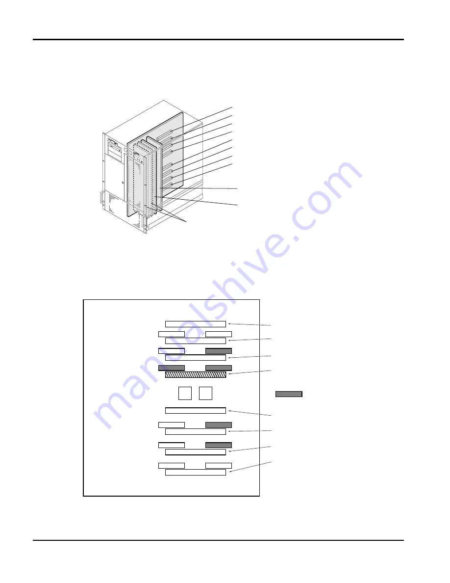
Figure 13

Memory and CPU Slots

Each CPU is numbered and corresponds to a numbered VRM. Install the CPUs in the order shown below in 
Figure 14 CPU/VRM Installation Detail. Note: This detail is for one CPU installed, minimal configuration.

Figure 14

CPU/VRM Installation Detail

Processor slot #4
Processor slot #3
Processor slot #2
Processor slot #1

Processor slot #5
Processor slot #6
Processor slot #7
Processor slot #8

Memory Expansion board #1
(Memory slot x 32)

Memory Expansion board #2
(Memory slot x 32)

Memory Termination Cards
(Option Memory Slot #3, 4)

VRM #3

VRM #2

VRM #1

VRM #5

VRM #6

VRM #7

VRM #8

VRM #4

Processor Slot #4

Processor Slot #3

Processor Slot #2

Processor Slot #1

= Default VRM
   setting

Processor Slot #54

Processor Slot #6

Processor Slot #7

Processor Slot #8

Summary of Contents for VisionBase 8880R

Page 1: ...Hitachi VisionBase 8880R Server Product Guide ...

Page 2: ...t you keep separate permanent written records of all important data and perform periodic backups Data may be lost or altered in virtually any electronic memory product under certain circumstances Therefore Hitachi PC assumes no responsibility for data loss or data otherwise rendered unusable whether as a result of improper use repairs defects or any other causes Hitachi PC assumes no responsibilit...

Page 3: ...tem Environment Setting 20 Notes on Use 21 Setup Menu 22 Flow of the Setup Menu Operation 22 Starting the Setup Menu 23 Setup Menu Screen 24 Steps for Setting the Setup Menu 26 What You Can Do on the Main Menu 26 What You Can Do on the Advanced Menu 28 What You Can Do on the Security Menu 33 What You Can Do on the Boot menu 34 What You Can Do on the Exit Menu 35 Notes on the Setup Menu 36 ISA Conf...

Page 4: ... the ICU Settings to Defaults 50 List of Utility Settings 50 3 Error Information 53 POST Error 53 System Beeps 54 4 NT Drivers and Limitations 55 Windows NT Driver Recommendations 55 Multiprocessor system module 55 Cautions and Limitations 55 Installing Windows NT 55 5 Related Document and Specification 57 Related Document 57 Environment Specification 57 ...

Page 5: ...inal technology System Specifications The Hitachi VisionBase 8880R Server system has four 4 independent 64 bit PCI busses See the table below for the system specifications CPU PentiumII Xeon 400 450 MHz x 8 1 2MB L2 Cache CPU Bus frequency 100 MHz PCI Bus frequency 33 MHz Memory Std Max 4 way Interleave 512 MB 16 GB 32 GB with 256MB DIMM SSTL SDRAM DIMM 4 Memory boards 2 Standard 2 Optional 32 DIM...

Page 6: ...Hot swappable disk bay compliant SCSI backplane 5 25 inch bay x 3 High Availability Redundant cooling fan Redundant power supply Hot Swap HDDs SVP Hardware Power Supply 3 1 Redundant power supply 550W for each P S unit Size 430 W x 640 D x 756 H mm 17 U Approx 17 x 25 x 30 Weight Between 70 100 kg Approx 175 250 lbs CPU PentiumII Xeon 400 450 MHz x 8 1 2MB L2 Cache ...

Page 7: ...Ch 1 Hardware Hitachi VisionBase 8880R Server 3 ...

Page 8: ... to assist you in accessing and turning on the power supplies NOTE Ensure direct power switch is in the OFF or normal position Figure 1 Accessing the Power Supplies 1 Figure 2 Accessing the Power Supplies 2 1 Remove the Power Supply cover by opening the HDD bay door using the key and then unscrewing and removing the 2 screws located at the bottom of the HDD bay on the metal tabs See Figure 1 Acces...

Page 9: ...of the features listed in the following table Item Feature Description 3 5 inch Diskette Drive A Activity LED When lit it indicates the drive is in use B Ejector button When pressed it ejects the diskette Front Panel LEDs and Indictors C Front panel LCD It displays information about the system and can also be controlled using the Menu Switch I D Main Power Switch Press this switch to turn on the p...

Page 10: ...te system error it may be in a warning state M Warning LED yellow When illuminated it indicates one of the following recoverable errors This is only for redundancy cases ECC 1 bit CPU error Memory Bus error HDD error Temperature is high Fan failure Power Supply failure N Reset This Reset is for system maintenance only and is not a Hardware Reset Switch O Error LED red When illuminated it indicates...

Page 11: ...to use an external disk unit 2 When the Direct Boot Switch is turned On and the system has power it will allow the system to automatically boot without pressing the Power Switch manually Server I O Panel A Parallel Interface Connector H USB Connector B ICMB Connector See note 1 I PTL Connector Test connector not in use C Keyboard Connector J VGA Interface Connector D Mouse Connector K Option Slots...

Page 12: ...g the alternating current AC power cord from each power supply or wall outlet 4 Label and disconnect all peripheral cables attached to the I O panel on the back of the server 5 Provide some electrostatic discharge ESD protection by wearing an antistatic wrist strap attached to chassis ground of the server any unpainted metal surface when handling components Warnings and Cautions Only a qualified s...

Page 13: ...sy cabling from the main board 3 Lift the fan assembly straight up by placing your fingers under the front lip of the fan assembly The fan assembly is attached to the chassis by 2 tab style latches shaded As soon as you have lifted the fan assembly high enough so it is clear of the latch tabs you may gently pull the assembly towards you to remove it completely 4 The Option slots PCI ISA are now ex...

Page 14: ... option boards Usage X recommend N don t install Usage X recommend N don t install Maximum Installation PCI 64 bit 15 14 13 12 11 10 9 8 7 6 5 4 3 2 1 VGA board S3 Trio64 V2 DX 1 N N N N N N N N N N N N N N X SCSI board Symbios SYM8751SP 4 N N N N N N N N X X X N N X N Disk array controller Mylex DAC960PU 3 N N N X N N N X N N N X X N N Fiber Channel 1 X X X N X X X N X X X N N N N Ethernet card 1...

Page 15: ...C Customer Service and Support Representative for a list of approved drives that can be installed in the server To access the Hard Disk Drive bay unlock the door by inserting the key and turning to the left or counter clockwise Accessing the HDD bay and device locations are referenced in the following Figures Figure 9 Accessing the Hard Disk Drives Figure 10 Hard Disk Drive Bays Cooling Fan Access...

Page 16: ...ull the assembly toward you to fully disengage the drive from the backplane connector 3 Carefully slide the assembly out of the bay and place it on an antistatic surface Proceed to step 4 if you are installing or replacing a HDD Figure 11 Removing Installing a HDD 4 Insert the HDD into a carrier and secure it into position with 4 screws as shown in Figure 12 Mounting the HDD Carrier 5 Orient the c...

Page 17: ...s and cabling Do not use the same cabling as the Internal CD ROM Some specific hard disk drive designs require electrical isolation of the drive from the chassis or other ground paths These drives are usually clearly labeled with this requirement on the drive Failure to isolate this type of drive from the ground path will result in unpredictable operation of the drive including severely impacted p...

Page 18: ...This detail is for one CPU installed minimal configuration Figure 14 CPU VRM Installation Detail Processor slot 4 Processor slot 3 Processor slot 2 Processor slot 1 Processor slot 5 Processor slot 6 Processor slot 7 Processor slot 8 Memory Expansion board 1 Memory slot x 32 Memory Expansion board 2 Memory slot x 32 Memory Termination Cards Option Memory Slot 3 4 VRM 3 VRM 2 VRM 1 VRM 5 VRM 6 VRM 7...

Page 19: ...MMs at a time Base configuration comes with 1GB 128MB x 8 pcs of memory using 128MB of DIMMs The table below summarizes the memory configurations Total Memory 4 0GB Total Memory 3 5GB Total Memory 3 0GB Total Memory 2 5GB Total Memory 2 0GB Total Memory 1 5GB Total Memory 1 0GB Default Configuration Total Memory 512MB DIMM Socket Number DIMM Socket Sets Memory Expansion Board Number X X X X X X X ...

Page 20: ...mory DIMM 128MB DIMMs 256MB DIMMs SDRAM SSTL interface DIMM Buffer Error correction ECC CPU Memory Expansion Board 1 Memory Expansion Board 2 Memory Expansion Board 3 optional Memory Expansion Board 4 optional Memory Riser Board Connector 2A 15 10 7A 6A 11 14 3A 4A 13 12 5A 8A 9A 16 1A 1B 16 9B 8B 5B 12 13 4B 3B 14 11 6B 7B 10 15 2B Set A Set B Front Side System Unit Right Side ...

Page 21: ...ings Below is the default jumper setting for the system board as shipped from the factory Figure 16 System Board Default Jumper Settings VRM 3 VRM 2 VRM 1 JP1 JP21 short jumper JP01 JP24 JP29 JP25 VRM 5 VRM 6 VRM 7 JP25 JP24 JP29 JP31 JP27 VRM 8 VRM 4 JP31 JP27 ...

Page 22: ...DEC21152 PIIX4e Super I O PC87307 DS1230 NVRAM DS1230 uSMC 8 8 SEG2 SEG1 SW1 SW2 SW3 SW4 SW5 SW7 SW6 LED5 SW1 SW2 SW3 SW4 SW5 SW7 SW6 LED4 LED3 LED2 LED1 12V 5V 3 3V 5V 12V ON ON OFF OFF 1 2 3 4 5 6 7 8 1 2 3 4 5 6 7 8 1 2 3 4 5 6 7 8 1 2 3 4 5 6 7 8 uSMC uSMC Firmware APIC APIC APIC APIC BIOS PCI 15 PCI 1 PCI 16 PCI 17 PCI 18 PCI 19 ISA 2 ISA 1 Shared Riser Connector ...

Page 23: ...an ISA board you need to conduct system environment setting There are two capabilities provided for system environment setting the Setup Menu and the ISA Configuration Utility ICU which must be executed in the following procedure Built in devices must be added or exchanged by maintenance personnel only Be sure to avoid removing the cover and installing removing built in devices Otherwise operation...

Page 24: ...m information checking only Memory capacity checking only Advanced Menu Resetting the setup data Setting initial diagnosis for ROM Setting PCI Setting I O devices Console redirection unsupported Setting extended multiprocessor configuration table Setting I O APIC mode Setting memory gap Setting parity check for PCI Setting memory test Setting 4GB or more caching for main memory Setting large capac...

Page 25: ...IRQ and ROM addresses See the manual for each board PCI Board If you use Windows NT use Auto Select in the Setup Menu to set IRQ setting values for extended boards conforming to the PCI specifications ISA Board When setting system environment for an ISA board check whether or not the disk attached to the board contains the CFG file The CFG files for a communication board PC CH2100 and an ISDN boar...

Page 26: ... Menu operation is as follows You can use and keys to switch between menus between Main and Advanced between Advanced and Security between Security and Boot and between Boot and Exit Use the key to return from a submenu to the original menu PCI Configuration I O Device Configuration Console Redirection Hard Drive Start the Setup Menu Main Menu Submenus IDE Menu unsupported System Information Esc k...

Page 27: ...re the key is pressed terminate the OS and then restart the system equipment Some type of OS such as Windows NT requires special operation such as shutdown Check the manual of your OS F2 PhoenixBIOS Setup Utirity F1 Help Select Item Select Menu ESC Exit Change Values Enter Select F9 Setup Defaults F10 Save and Exit Sub Menu Item Specific Help Main Advanced Security Boot Exit System Time System Dat...

Page 28: ... items marked then press the key The submenu is displayed 3 Help The help information for the selected setting item is automatically displayed 4 Key guidance The usage of each key is displayed PhoenixBIOS Setup Utirity F1 Help Select Item Select Menu ESC Exit Change Values Enter Select F9 Setup Defaults F10 Save and Exit Sub Menu Item Specific Help Main Advanced Security Boot Exit System Time Syst...

Page 29: ...or to the top of the setting screen Moves the cursor to the bottom of the setting screen Ten Key Decreases the setting value by 1 Ten Key Increases the setting value by 1 Moves the cursor to the left on the menu bar Moves the cursor to the right on the menu bar Displays the submenu Executes the command Loads the default Saves the settings and exits the Setup Menu Exits the submenu Moves to the Exi...

Page 30: ...ursor to Security to display the Security menu 5 Moving the cursor to Boot displays the Boot menu See What You Can Do on the Boot menu on page 34 if necessary to set up the Boot menu and then return to the Main menu 6 When you finished changing the settings press the Exit or key to exit the Setup Menu See What You Can Do on the Exit Menu on page 35 Before exiting the Setup Menu insert ISA Configur...

Page 31: ...for each drive Disabled default for Legacy Diskette B 360KB 5 unsupported 1 2MB 5 unsupported 720KB 3 1 44MB 3 default for Legacy Diskette A Primary Master Slave These areas are for setting IDE hard disk Because the Hitachi VisionBase 8880R Server does not support IDE do not change the settings Type Auto Multi Sector Transfers Disabled LBA Mode Control Disabled 32 Bit I O Enabled Transfer Mode Sta...

Page 32: ...ot to conduct initial diagnosis for ROM Be sure to leave the default setting No as is No Does not conduct initial diagnosis default Yes Conducts initial diagnosis NOTE Reset Configuration Data and Execute ROM Diagnostic are used solely for maintenance purposes These two areas shall not be changed Hitachi PC assumes no responsibility for any failures or inconveniences caused by changed values in th...

Page 33: ...orresponds to slots 7 11 15 and 19 Line 2 corresponds to slots 1 4 8 12 and 16 Line 3 corresponds to slots 2 5 9 13 and 17 Line 4 corresponds to slots 3 6 10 14 and 18 Current Resources The resource interrupt level currently assigned to the PCI slot is displayed I O Device Configuration Serial port 1 2 Used to set built in serial ports 1 and 2 built in COM ports 1 and 2 In ordinary circumstances u...

Page 34: ...ayed when ECP is set in the Mode item Floppy disk controller Used to make settings for the built in floppy disk drive controller In ordinary circumstances use the default settings Floppy disk controller Disabled Enabled default Local Bus IDE adapter Used to make settings for the IDE controller In ordinary circumstances use the default settings Local Bus IDE adapter Disabled Enabled default NOTE Do...

Page 35: ... Enable memory gap Used to specify whether or not to use part of memory addresses memory gap for extended boards Use the default Disabled Disabled Not to be used on extended boards default Enabled To be used on extended boards PCI Data Parity Used to set parity check for PCI bus In ordinary circumstances use the default setting Enabled Enabled Conducts a parity check default Disabled Conducts no p...

Page 36: ...t Enabled Allocates Large Disk Access Mode Unsupported Used to set an access method for the IDE hard disk This setting is unsupported Use the default DOS DOS Use in MS DOS default Other Use in an OS other than MS DOS Disk Write Cache Unsupported Used to set write cache for the IDE hard disk This setting is unsupported Use the default Enabled Disabled Enabled default Speaker Volume Used to set the ...

Page 37: ...ord is set Clear is displayed when a password is set Enabled is displayed Set Supervisor Password Used to set a supervisor password with 8 characters Set User Password When a supervisor password is set set a user password with 8 characters Password on boot Specify whether or not to have the system prompt you to enter a password at startup Disabled No prompt for password entry Enabled Prompt for pa...

Page 38: ...compatible SCSI boards such as PC CS7331 or PC CS7231A are installed more devices might be displayed Hard Drive IDE Hard Disk Drive Used to specify the order of booting for the hard disk Check whether the display is the same as the following 1 Bootable Legacy Device NOTE When PC98 compatible SCSI boards such as PC CS7331 or PC CS7231A or IDE devices are installed more devices might be displayed An...

Page 39: ...e setup data The system equipment is restarted After changing setup data select Exit Discarding Changes and then press key The following screen is displayed To exit without recording the setup data select Yes and press key To continue processing without recording the data either select No or press key to return to the Exit menu Exit Saving Changes Exit Discarding Changes Load Setup Defaults Discar...

Page 40: ...forming to Plug and Play to be used correctly in the system equipment When you expand your system make appropriate settings in the Setup Menu and use the ICU to perform configuration The settings are stored in nonvolatile memory of the system equipment It is recommended that the user configure the ISA card first using the ICU before installing it in the system In one of the following cases start t...

Page 41: ... Some improper operation can make ICU floppy disks unusable In such a case create new backup disks before using the existing backup disks Built in devices must be added or exchanged by maintenance personnel only Be sure to avoid removing the cover and installing removing built in devices Otherwise operation of the equipment shall not be guaranteed Check resource usage status Add an ISA board Chang...

Page 42: ...n I O devices and memory used for direct high speed data transfer Memory address Memory area reserved for specific extended boards If two extended boards use the same resource one of the two might not operate at all or the system equipment might not operate as expected The ICU can prevent duplicate allocation like this allowing you to check allocation status Starting the ICU Create the following b...

Page 43: ... topic you want and choose Help You can also display Help for the command currently being executed Choosing Help in the dialog box will display explanations Key Function letter When you want to choose a button with an underlined letter you can substitute it by entering that letter while holding down key For example instead of opening the File Menu and choosing Save you can enter while holding down...

Page 44: ...isplayed 3 A termination message is displayed Choosing the OK button will display the following screen Pressing any key will terminate the ICU 4 Unplug the ICU program disk and then turn the power off Motherboard System Devices PCI Card VGA Controller PCI Card SCSI Controller PCI Card Unknown Card PCI Card IDE Controller ISA Configuration Utility File Configure View Advanced Help Card Configured I...

Page 45: ...nded boards Resources currently in use by the system equipment are displayed in the System Resource Usage dialog box 2 After checking choose Close Motherboard System Devices PCI Card VGA Controller PCI Card SCSI Controller PCI Card Unknown Card PCI Card IDE Controller ISA Configuration Utility File Configure View Advanced Help Card Configured In System Add Remove Modify View System Resources Card ...

Page 46: ...100 1 Start the ICU 2 In the ISA Configuration Utility window choose the Add button Motherboard System Devices PCI Card VGA Controller PCI Card SCSI Controller PCI Card Unknown Card PCI Card IDE Controller ISA Configuration Utility File Configure View Advanced Help Card Configured In System Add Remove Modify View Resources assigned to Motherboard System Devices Close Print To File Help System Reso...

Page 47: ... will save the system configuration data file SYSTEM IMG into DISK2 11 A termination message is displayed Turn the power off 12 Referring to the manual attached to the ISA board change the setting for the extended board to the values recorded in step 7 13 Install the extended board on the expansion slot ISA When you restart the system equipment the extended board is usable NOTE When you need to in...

Page 48: ...one when You want to use resources that are being used by an extended board already installed You want to change setting values NOTE When you need to install an extended board in or remove it from the system equipment call the maintenance personnel 1 Remove the extended board in advance After changing the settings you need also to change the settings for short pins on the extended board See the ve...

Page 49: ...rd should be deleted choose OK 4 The ISA Configuration Utility window is displayed Check that the selected extended board has been deleted 5 Exit the ICU 6 Turn off the system equipment and remove the extended board from the system equipment Built in devices must be added or exchanged by maintenance personnel only Be sure to avoid removing the cover and installing removing built in devices Otherwi...

Page 50: ...case take the following steps for resetting If the display is normal no resetting is required 1 Make a backup copy from the ICU program disk that has been saved 2 Start the ICU 3 The ISA Configuration Utility window is displayed The names of ISA boards incompatible with Plug and Play are changed to Unknown Card NOTE Unknown Card is displayed for RAID controller PC CA7112 Unless Unknown Card is dis...

Page 51: ...again remove all boards other than those already installed as standard boards 2 Start the ICU 3 In the ISA Configuration Utility window choose the Advanced menu 4 A screen that looks like the following is displayed On that screen choose Load Image 5 In the Load Image File window now displayed choose a from Drives and SYSTEM IMG from Filename The SYSTEM IMG file in ICU DISK2 in drive A restores the...

Page 52: ... or change an extended board No more IRQ values can be added No more DMA values can be added No more Memory address values can be added No more I O Port values can be added Explanation Depending on the resource to be added or changed one of the above messages is displayed The maximum allowable value for each function has been exceeded The maximum allowable value for each resource is as follows Int...

Page 53: ...at are not easy to see because characters are displayed in black in gray background While you are operating the ICU sometimes characters might not be displayed properly or part of some ruled lines might be missing in some windows or dialog boxes but nothing is wrong with the operation of the ICU Referring to diagrams of windows and dialog boxes in this manual keep on operation Japanese characters ...

Page 54: ...gs top defaults 2 List of Utility Settings below change the settings to Hitachi VisionBase 8880R Server settings List of Utility Settings ICU ISA Configuration Utility This table defines the ICU factory default settings Item Default Setting Value Motherboard System Device ISA Bridge Fixed Configuration System Peripheral Fixed Configuration RAM Controller Fixed Configuration DMA Controller Fixed Co...

Page 55: ...378 37f PCI Card IDE Controller IDE Controller Fixed Configuration Unknown Controller IRQ DMA Memory Hex I O port Hex Enabled None None None None Bridge Controller IRQ DMA Memory Hex I O port Hex Disabled None None None None PCI Card VGA Controller VGA Controller IRQ DMA Memory Hex I O port Hex Fixed Configuration None None A000 bffff C000 c7fff Fd000000 Fdffffff 3b0 3bb 3c0 3df Item Default Setti...

Page 56: ... max None Alternate CHS Mapping Device Selections CD ROM DAT MO ID 3 4 5 Sync Rate Mbytes sec Width bits Disconnect Read Write I O Timeout sec Scan Bus Scan for SCSI LUNs Que Tags Host Adapter ID 7 Sync Rate Mbytes sec Width bits Disconnect Read Write I O Timeout sec Scan for Device at Boot time Scan for SCSI LUNs Que Tags Format Verify 10 8 On 10 Yes Yes On 40 16 On 10 Yes Yes On Change Adapter S...

Page 57: ...0250 50 System battery is dead Replace and run SETUP Battery 0251 51 System CMOS checksum bad Default configuration used CMOS configuration 0260 60 System timer error Timer 0270 70 Real time clock error Real time clock 0271 71 Check date and time setting BIOS setup 02B0 B0 Diskette Drive A error 02B1 B1 Diskette Drive B error 02B2 B2 Incorrect Drive A type run SETUP BIOS setup 02B3 B3 Incorrect Dr...

Page 58: ...t you may encounter and the error that is being reported 0505 05 Expansion ROM not initialized PCI controller Name BIOS setup 0506 06 Warning IRQ not configured PCI controller Name BIOS setup 0602 02 Serial port x configuration error device disabled BIOS setup Beep pattern 7 Seg Port 80 Error 1 2 Search for option ROMs Check sum failure 1 3 1 1 20 DRAM refresh failure 1 3 1 3 22 Keyboard failure 1...

Page 59: ...llowing steps for a successful Windows NT installation Windows NT 4 0 Enterprise Edition only supports a 4 or 8 way multiprocessor system If your system has more than 3 5GB of memory you must complete the following steps for a successful Windows NT installation 1 Enter the BIOS Setup utility by pressing F2 during the system boot 2 Select Advanced Menu Windows NT 4 0 Install Mode 3 Change the param...

Page 60: ...Ch 4 NT Drivers and Limitations 56 Hitachi VisionBase 8880R ...

Page 61: ...s 3 power supply Maximum configuration Input Requirements per power supply Low range High range Rated Input Voltage 100 to 120 V 200 to 240 V Rated Input Frequency 50 60 Hz 50 60 Hz Rated Input Current less than 10A Power Supply Output Power per power supply Low range High range Rated Steady State Power Maximum Peak Power 1 650 W 550W x 3 1 Temperature Range Operating 5º 40º C Shipping 30º 60º C R...

Page 62: ...Ch 5 Related Document and Specification 58 Hitachi VisionBase 8880R ...

Reviews: