CHAPTER 1
GENERAL INFORMATION
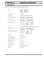
1. Specifications ......................................................... 1-1
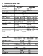
2. Comparison with Previous Model .......................... 1-2
2.1
Comparison of Specifications ......................... 1-2
2.2
Comparison of ICs .......................................... 1-2
CHAPTER 2
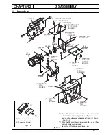
DISASSEMBLY
1. Procedure .............................................................. 2-1
CHAPTER 3
ELECTRIC CIRCUIT
ADJUSTMENT
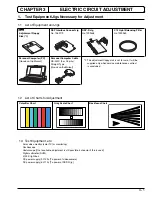
1. Test Equipment/Jigs Necessary for Adjustment .... 3-1
1.1
List of Equipment and Jigs .............................. 3-1
1.2
List of Charts for Adjustment ........................... 3-1
1.3
Test Equipment, etc. ....................................... 3-1
2. Before Stating Adjustment ..................................... 3-2
2.1
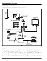
Connections for Adjustment ............................ 3-2
2.2
Notes ............................................................... 3-2
2.3
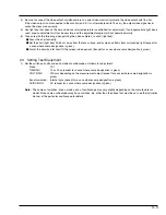
Setting Test Equipment ................................... 3-3
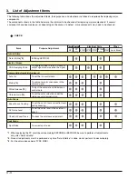
3. List of Adjustment Items ......................................... 3-4
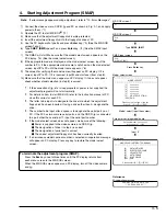
4. Starting Adjustment Program (SMAP) ................... 3-5
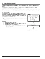
5. Data Initilize Procedure .......................................... 3-6
5.1
Data Initilize ..................................................... 3-6
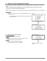
6. Electronic Volume Adjustment Procedure ............. 3-7
6.1
CDS Sampling Pulse Adjustment ................... 3-7
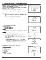
7. Camera Adjustment (Adjustment) Procedure ........ 3-8
7.1
Auto Iris Control Adjustment ........................... 3-8
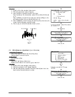
7.2
Matrix Adjustment [For TYPE S/SE] ............... 3-8
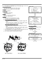
7.3
White Balance Adjustment [For TYPE S/SE] .. 3-9
7.4
Chroma Gain Adjustment [For TYPE S/SE] .... 3-10
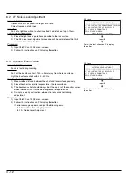
8. Autofocus Adjustment Procedure .......................... 3-11
8.1
Zoom/Focus Tracking Adjustment .................. 3-11
8.2
AF Noise Level Adjustment ............................. 3-12
8.3
Check of Zoom Trace ...................................... 3-12
9. Spot Noise Adjustment Procedure ......................... 3-13
9.1
Spot noise Adjustment .................................... 3-13
10. Error Messages ...................................................... 3-14
10.1 Error massage of Electronic Volume and
Camera Adjustment ........................................ 3-14
10.2 Error massage of Autofocus Adjustment ....... 3-15
10.3 Error massage of Spot Noise Adjustment ...... 3-15
10.4 Troubleshooting of Autofocus ......................... 3-16
(1)
No zoom and focus operation ....................... 3-16
(2)
No focus lens operation ................................ 3-18
(3)
No zoom operation ....................................... 3-19
(4)
No autofocus operation ................................. 3-20
(5)
Subject is greatly out-of-focus
when zoomed ................................................ 3-21
CONTENTS-1
CHAPTER 4
EXPLODED VIEW
1. Exploded View ....................................................... 4-1
CHAPTER 5
REPLACEMENT
PARTS LIST
1. Mechanical Parts List ............................................. 5-1
2. Electrical Parts List ................................................ 5-2
CHAPTER 6
SCHEMATIC, CIRCUIT
BOARD AND BLOCK
DIAGRAMS/MICROPRO
CESSOR PIN FUNCTION
TABLES
Schematic Diagrams
Connection Diagram .................................................... 6-1
Waveforms ................................................................... 6-1
Sensor [SP] .................................................................. 6-2
Process [PC] (For Display) .......................................... 6-3
Process [PC] (For Printing) <A-a> ............................... 6-4
Process [PC] (For Printing) <A-b> ............................... 6-5
Switching Regulator [CSR] .......................................... 6-6
Circuit Board Diagrams
PC -Side A/B- .............................................................. 6-9
Identification of Parts Location ............................... 6-7
SP -Side A/B- ............................................................... 6-10
Identification of Parts Location ............................... 6-7
CSR -Side A/B- ............................................................ 6-10
Identification of Parts Location ............................... 6-8
Block Diagrams
Overall ......................................................................... 6-11
Microprocessor Pin Function Tables
Digital Microprocessor (IC1201: D-µP) ........................ 6-12
Contents


