6 - 2
Adjustment > Preparations for Adjustment
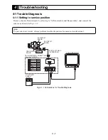
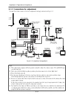
Fig. 6-1-1 Connections for Adjustment
6-1-3 Connections for adjustment
Connect the video camera to the test equipment and jigs as shown in Fig. 6-1-1
Note:
1) The adjustment program will not operate normally unless the video camera, PC and DSP-R jigs
are all turned on.
2) Take care with the following when pointing the video camera at a chart (light box):
a) Focus the chart correctly.
b) Set the chart (light box) 30-50 cm away from the lens surface, and avoid any effects from
surrounding light (except for a case where some designation is given).
3) Be sure to connect the video output of video camera to a color video monitor (terminate the video
output with 75 ohm):
If the video output is not connected to the monitor (and if it is not terminated with 75 ohm), the
output video signal level cannot be measured correctly.
4) Use light box that does not flicker and whose color temperature is controlled, for adjustment. If
an inappropriate light box is used, precise adjustment will not be possible, and the adjustment
program will not operate normally.
PG1601
VIDEO CAMERA
LIGHT
BOX
9PIN FLAT CABLE
(ACCESSORY)
1
9
DSP INTERFACE CONNECT JIG
1 2 3 4 5 6 7 8 9
RD
WHT
SD
BRW
GND
BRW
+B
BRW
GND
BRW
VIDEO
BRW
GND(VIDEO) BRW
EX. FV
BRW
GND
BRW
1
2
3
4
5
6
7
8
9
+
DC POWER
SUPPLY
(9V/3A)
GND
+
DC POWER
SUPPLY
(5V/1A)
GND
PERSONAL
COMPUTER
RS-231C
CABLE
DSP-R JIG
BLK
RED
CH1 CH2
COLOR
MONITOR
To VIDEO IN
TERMINAL
To
INPUT
To
OUTPUT
VECTORSCOPE
OSCILLOSCOPE
When using an
osilloscope only
BLK
WHT
YEL

