7 - 1
CHAPTER 7
APPENDIX
1.
SELF-DIAGNOSTIC FUNCTION
1.1
Overview
The camera/recorder has the following self-diagnostic
function.
Occasional defect self-diagnostic function (A mode)
Mechanical block self-diagnostic function
(B mode)
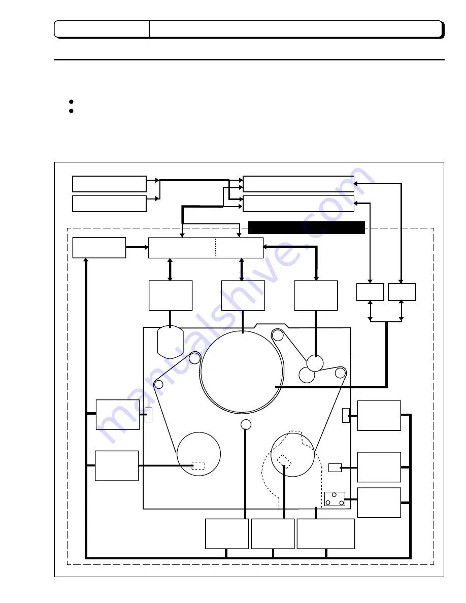
Fig. 1-1 Self-Diagnostic Coverage Range
CAMERA BLOCK
MIC UNIT
VIDEO SIGNAL
PROCESS CIRCUIT
AUDIO SIGNAL
PROCESS CIRCUIT
VIDEO
SIGNAL
AUDIO
SIGNAL
SERVO
CIRCUIT
SYSTEM CONTROL
CIRCUIT
TROUBLE
SENSOR
LOADING
MOTOR
CYLINDER
S30
CAPSTAN
MOTOR
TAKE-UP
END
SENSOR
EST
CASSETTE
HOLDER
SW
STG
TAB, ME, MP
TAPE
DETECT.
SW
EJT, UST, REW,
LST, FWD, HEC
MODE SW
RST
TAKE-UP
REEL
SENSOR
END LED
RSS
SUPPLY
REEL
SENSOR
ESS
SUPPLY
END
SENSOR
SELF-DIAGNOSIS COVER RENGE
Fig. 1-1 shows the self-diagnostic coverage range.
The self-diagnostic functions of the camera/recorder are
engaged by the system control (S) µP (IC0901) which
detects, memorizes and displays data related to defects in
the mechanical block control system.
LOD, UNL
CFG


