2-22
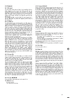
Stopping of head drum motor
This is monitored with the PG/FG signal. The signal is discharged
from the e.m.f. of the non-conducting spools of the head cylinder
motor, showing the position of the head cylinder.
Capstan motor fault
This is monitored with the FGD signal.
If one of the above sensor signals is not available, the recorder tries
to put the lift into the EJECT position.
Explanation of deck error codes and deck error status
The last error code is stored and remains in the EEPROM, even if the
recorder is disconnected from the mains.
The error code can be
erased
by pushing the CLEAR button on the
remote control.
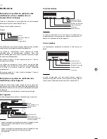
The display shows, for instance:
The left digit shows the error:
(e.g.: Error 2 = Capstan error)
Error table:
The 3 digits on the right represent the deck error condition:
(e.g.: 053 = during Play )
The error code can be reset in this step with the CLEAR key.
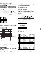
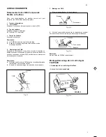
Step 01: Checking the drive positions
By pressing the SELECT key whilst Step 01 is flashing, the drive
position appears on the display.
The FTA signal from the photoelectric barriers which controls the
revolutions of the loading motor is used to check the drive condition.
The drive position is shown as a 3-digit decimal number by counting
the FTA pulses on the display.
(e.g. 213 = Play)
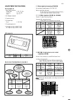
Table of drive positions:
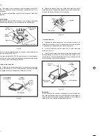
Function of the Init switch:
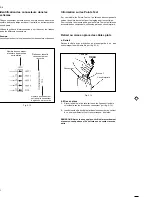
The diagram shows the function of the Init switch, depending on the
position of the deck. The number of FTA pulses is important for the
position of the drive.
Step 02: Display of the deck error codes
By pressing the SELECT key whilst Step 02 is flashing, the deck
error code is shown on the display.
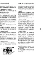
Checking the drive function
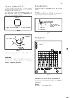
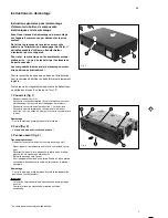
Loading and unloading time
The signal (FTA) of the photoelectric barrier which controls the
revolutions of the loading motor is used as a reference for the loading
and unloading time.
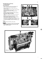
Stopping of supply or take-up reels
The tacho signals of the left (WTL) and right (WTR) winding disks are
used as control reference.
GB
Status
Position
(FTA dec)
Eject
007 +2/-2
Index
191 +0/-2
Stop
200 +4/-4
Play
213 +4/-4
Reverse
237 +2/-0
A
B
A: DC, 2 V/Div, 0.5 s/Div
B: DC, 2 V/Div, 0.5 s/Div
Eject
Cass down
I n d e x /
w i n d - r e w i n d
Play
Reverse
Init switch
FTA pulses
0
no error
1
threading error
2
no capstan pulses
3
tape broken
4
no pulses left reel
5
no pulses right reel
6
head motor error
Functiontable:
012 Standby
114 VISS write
211 Slowmotion 1/24
014 Autotracking
115 Viss erase
212 " " 1/14
031 Play-3
125 Tuner - Stopout
215 " " 1/7
034 Slow_reverse
126 Auto Remain Funct.
216 " " 1/2
041 Still Picture
130 ATTS Function
217 " " -1/24
042 Fast
168 Frame+
218 " " -1/14
044 Play-9
169 Frame-
219 " " -1/7
045 Eject
170 Play-11
220 " " -1/2
046 Play9
171 Play-7
222 Edit Record
047 Play-1
172 Play-5
223 Align of Gap
048 Pause
173 Play5
238 Pause
050 Rewind
174 Play7
239 SPC align
052 Wind
175 Play11
246 Edit Pause
053 Play
196 Tuner - Eject
247 Slow motion 1/10
054 Stop out
197 Standby Eject
248 " " 1/18
055 Record
199 Audio Dubbing
249 " " -1/10
112 Index next
202 Audio Dubb. Pause
250 " " -1/18
113 Index previous
206 Reset Tapecounter
253 Key Released
Summary of Contents for VTFX940EUKN
Page 6: ......
Page 30: ......
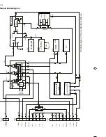
Page 83: ...3 1 3 1 Wiring Diagram Motherboard ...
Page 85: ...3 3 3 3 Block Diagram Video ...
Page 87: ...3 5 3 5 Block Diagram Audio Stereo ...
Page 88: ...3 6 3 6 Supply Voltages and Bus Diagram ...
Page 91: ...3 9 3 9 Block Diagram Central Control AIO1 AIO2 OPTION ...
Page 92: ...3 10 3 10 Mother Board solder side CLOCK ADJUST 4769 ...
Page 93: ...3 11 4769 E10 ...
Page 94: ...3 12 ...
Page 119: ...THE UPDATED PARTS LIST FOR THIS MODEL IS AVAILABLE ON ESTA ...
Page 120: ......

