4
! " -
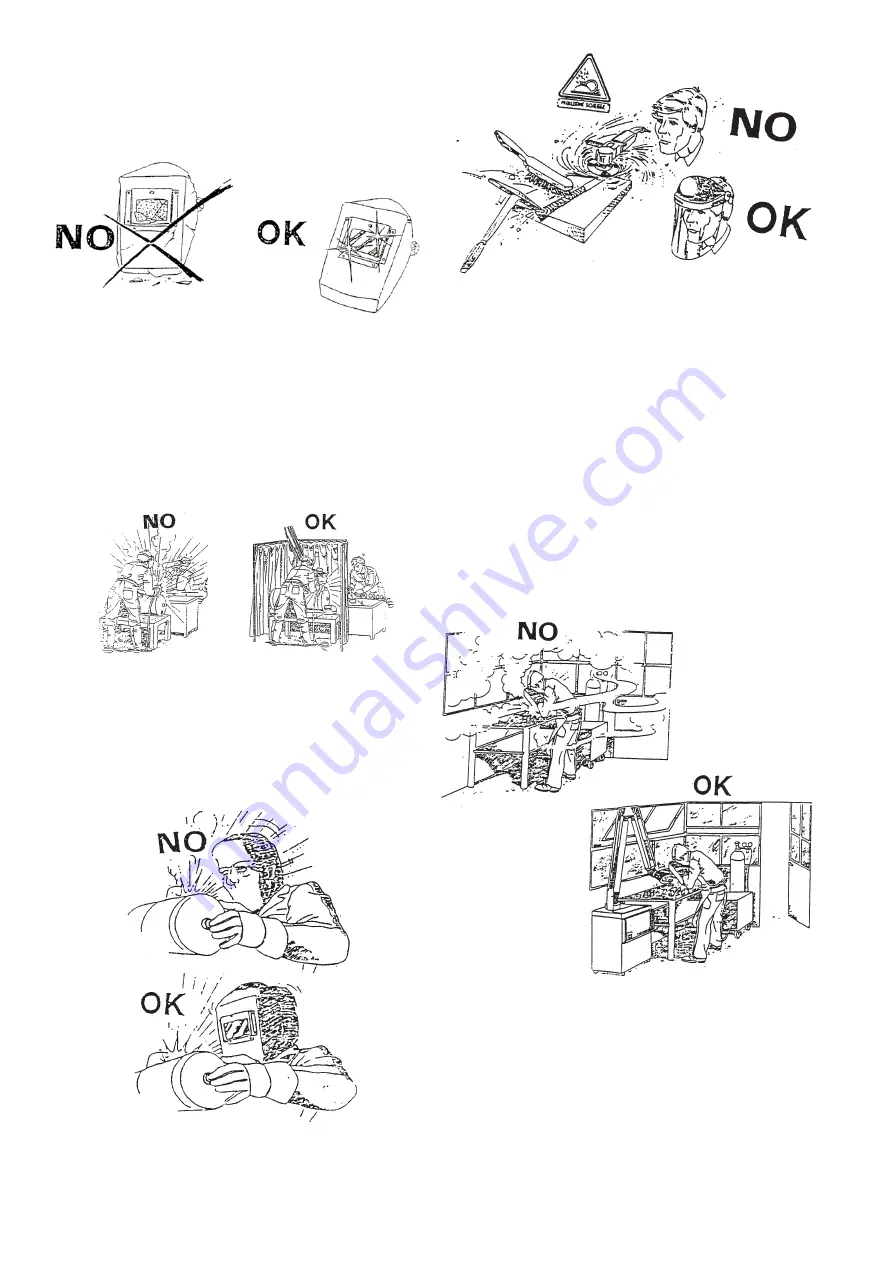
placed when incandescent spatters and de-
. !/
with coated plates that emit toxic fumes when
<
- Welding should be done in a closed area
that does not open onto other working areas,
in order to protect all workers against radia-
'
provided, the welding area must be delimi-
ted by protective screens painted in opaque
black large enough to restrain the visibility of
1# J3
- Remove all chlorinated solvents from the
! ! X -
nated solvents decompose when exposed to
- Never, under any circumstances, look at
an electric arc without suitable eye protection
1# [3
- Always wear protective goggles with tran-
sparent lenses to prevent splinters or other
1#
\3
- Adequate local exhaust ventilation must
'
through a mobile hood or through a built-
in system on the workbench that provides
exhaust ventilation from the sides, the front
and below, but not from above the bench so
exhaust ventilation must be provided toge-
ther with adequate general ventilation and
air circulation, particularly when work is done
1#]3 0
stain or soreness to the eyes, the nose or the
throat may be cause by inadequate ventila-
tion; work must be stopped immediately and
all necessary steps must be taken to provide
- Welding process must be performed on
metal coatings thoroughly cleaned from la-
yers of rust or paint, to avoid production of
" !
!
- Do not weld metal or painted metal con-
taining zinc, lead, cadmium or beryllium un-
less the operator, or anyone else subjected to
the fumes, is wearing respiratory equipment
<
#@
#J
#[
#\
#]
Summary of Contents for W200
Page 13: ...12 1 3 ª µ µ µ 1 3 J ª ...
Page 14: ...13 1 3 1 3 ª 1 3 º 1 J3 1 3 J ...
Page 15: ...14 1 3 1 3 1 3 ...
Page 16: ...15 1 3 1 3 À ª À J ...
Page 18: ...17 ª µ 1 3 ...
Page 19: ...18 1 3 J ª 1 3 Á Á ª 1 3 º Á Â Á 9µ µ µ µ J Â Á Â Â Á Â Â Á Â J Â Á Â Â Á Â 8 7 1 2 5 6 3 4 ...
Page 20: ...19 Á 1 3 1 3 Ã µ µ º ...
Page 21: ...20 J 1 3 À J 3 J 3 Å Æ J 0 Å 2 X 4 ...
Page 32: ...31 13 0 PARTS DRAWINGS EXPLOSIONZEICHNUNG W130 ...
Page 34: ...33 14 0 PARTS DRAWINGS EXPLOSIONZEICHNUNG W160 ...
Page 36: ...35 15 0 PARTS DRAWINGS EXPLOSIONZEICHNUNG W200 ...
Page 38: ...37 16 0 WIRING DIAGRAM SCHALTPLAN W130 PCB1 PCB2 PCB3 FAN 220 230V 50 60HZ TA HALL PROBE ...
Page 39: ...38 PCB1 PCB2 PCB3 FAN 220 230V 50 60HZ TA HALL PROBE 17 0 WIRING DIAGRAM SCHALTPLAN W160 ...
Page 40: ...39 18 0 WIRING DIAGRAM SCHALTPLAN W200 ...
Page 41: ...40 HITACHI HITACHI Á HITACHI W130 HITACHI W160 Ú µ Á µ Å µ Å Å J Å 1 3 1 3 1 3 1 3 Ë ...
Page 42: ...41 9 0X9 µ µ µ µ µ µ 1 3 µ µ µ Å ...
Page 43: ...42 ÀÀÀÀÀÀÀ ÛÛÛÛÛÛÛÛÛÛ ÛÛÛÛÛÛÛÛÛ ÛÛÛÛÛÛÛÛ ÛÛÛÛÛÛÛÛÛÛÛÛ ...
Page 45: ...77611267 ...


