--- 12 ---
9. PRECAUTIONS IN DISASSEMBLY AND REASSEMBLY
The [Bold] numbers in the following descriptions correspond to the item numbers in the parts list of the Model
WF 4V.
9-1. Disassembly and Reassembly of the Feeder Unit and Handling Precautions
9-1-1. Disassembly
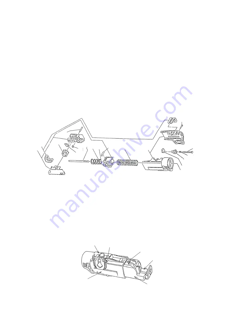
(a) Loosen the four Tapping Screws (W/Flange) D4 x 20 [13] securing Slider Case (A) [12] and remove Slider
Case (A) [12] from Slider Case (B) [12]. With Slider Case (A) [12] removed, the built-in parts and assemblies
can be taken out as they are.
* Since Spring (A) [11] is fitted in compression, removing Slider Case (A) [12] will cause the Slider Ass'y to
jump out. So be sure to hold the Slider Ass'y while loosening the Tapping Screw (W/Flange) D4 x 20 [13] to
prevent it from jumping out. Also take care not to lose the Roller [10] housed in the Slider Case.
(b) Loosen the two Tapping Screws (W/Flange) D4 x 25 [4] securing the Sprocket [3], Spring (B) [8], Slider Ass'y
(C) [1], Bit Guide [6] and Slider (B) [1] and remove them.
9-1-2. Reassembly
Simply reverse the disassembly procedure, while observing the following precautions.
(1) Make sure that the joint between the Slider (A)/(B) is completely aligned at the point marked (a) in Fig. 13 (as
this is essential for proper sliding).
(2) If the top surface (b) (Fig. 13) of the screw seat of Slider Case (A) is lower than Slider Case (B), it is likely to
result in improper sliding movement. Adjust top surface (b) of the screw seat of Slider Case (A) to be flush
with or a little higher than Slider Case (B).
Fig. 12
[1]
[2]
[3]
[4]
[5]
[6]
[7]
[8]
[9]
[10]
[11]
[12]
[13]
[14]
[15]
[16]
[17]
Slider Case (A)
Slider Case (B)
Slider (B)
Slider (A)
b
a
Fig. 13


