--- 13 ---
9-1-3. Tightening Torque
(1) Tapping Screw (W/Flange) D4 x 20 (25/32")
• • • • • •
20 5 kg
•
cm [1.96 0.49 N
•
m] (1.44 0.36 ft-lb)
(2) Tapping Screw (W/Flange) D4 x 25 (1")
• • • • • •
20 5 kg
•
cm [1.96 0.49 N
•
m] (1.44 0.36 ft-lb)
9-1-4. Confirmation After Reassembly
(1) Make sure that the Slider Ass'y moves smoothly within the Slider Case [12].
(2) Make sure that the collated screws feed correctly.
(3) Make sure that there are no lost or tilted screws when actually tightening.
9-2. Precautions in Disassembly and Reassembly of the Main Body
9-2-1. Disassembly
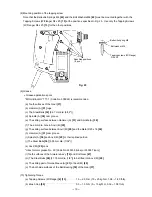
(1) Remove Handle Cover and Housing (B).
Remove the four Tapping Screws (W/Flange) D4 x 20 (25/32") secured to the Handle Cover. Then insert a
cutter along the joint between Housing (A) and Handle Cover, cut the Grip Tape [45] and remove the Handle
Cover. Remove the eight Tapping Screws (W/Flange) D4 x 20 (25/32") secured to Housing (B). After Housing
(B) has been removed, the parts inside can be removed individually or subassemblies.
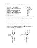
(2) Removal of mechanical parts
Lift Housing (A) while holding Anvil (M) [29] and Ball Bearing [39] of Spindle (A), and the Anvil section and
Hammer (A) [31] and Spindle (A) [38] sections can be separated from each other. Then remove the Second
Pinion Ass'y. Take care not to lose Washer (A) [40].
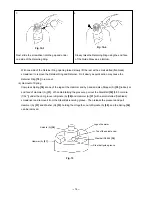
(a) Remove Anvil (M) [29]
Follow the procedure as shown on the next page to remove the Retainer Ring [18], Retainer [19], Guide
Spring [20] and Guide Sleeve (A) [21] in this order. Take care not to lose the two Steel Balls [28] [3.175
mm dia. (1/8")] fitted in the hole of Anvil (M) [29].
Hold the body and place a small slotted (flat-blade)
screwdriver at an angle to the Retainer and Retaining
Ring at the retaining ring gap.
Press down on the Retainer and Retainer Ring
with the screwdriver at the same angle.
Fig. 14-2
Fig. 14-1
1
2
Small slotted (flat-blade) screwdriver
Anvil (M) [29]
Retaining Ring [18]
Retainer [19]
Retaining ring gap
Guide Sleeve (A) [21]


