--- 19 ---
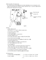
(8) Mounting position of the tapping screw
Note that the Belleville Springs M4 [43] and the Bolt Washers M4 [42] must be mounted together with the
Tapping Screws (W/Flange) D4 x 20 [13] at the positions specified in Fig. 25. Use only the Tapping Screws
(W/Flange) D4 x 20 [13] for the other positions.
(9) Grease
Grease application spots
*MOLUB-ALLOY 777-1 (Code No. 309922) is recommended.
(a) Tooth surfaces of the Gear [37]
(b) Hammer (A) [31] lugs
(c) The Steel Balls [32] [3.97 mm dia. (5/32")]
(d) Spindle (A) [38] cam groove
(e) The sliding surface between Hammer (A) [31] and Spindle (A) [38]
(f) The 6 mm dia. hole in Anvil (M) [29]
(g) The sliding surface between Anvil (M) [29] and the Metal D20 x 16 [24]
(h) Hammer (A) [31] cam groove
(i) Spindle (A) [38] and Anvil (M) [29] or their splined portion
(j) The Steel Balls [30] [5.55 mm dia. (7/32")]
(k) Anvil (M) [29] vane
*Hitachi motor grease No. 29 [Code No. 930035 (tube) or 930037 (can)]
(l) Tooth surfaces of the Armature Ass'y [70] and First Gear [47]
(m) The Steel Balls [28] [3.175 mm dia. (1/8")] to be fitted into Anvil (M) [29]
(n) The sliding part of Guide Sleeve (A) [21] of Anvil (M) [29]
(o) The both side surfaces of the Ball Bearing [39] of the Gear [37]
(10) Tightening Torque
(a) Tapping Screws (W/Flange) [4] [13]
• • • • • • • • • • • • •
1.5 --- 2.5 N
•
m (15 --- 25 kgf
•
cm, 1.08 --- 1.80 ft-lb)
(b) Brush Cap [55]
• • • • • • • • • • • • • • • • • • • • • • • • • • • • • • • • • • • • • • • • • • •
0.5 --- 1.5 N
•
m (5 --- 15 kgf
•
cm, 0.36 --- 1.08 ft-lb)
Tapping screws (W/Flange)
D4 x 20
Specified positions
(6 pcs.)
Belleville spring M4
Bolt washer M4
Fig. 25


