-16-
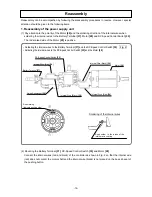
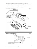
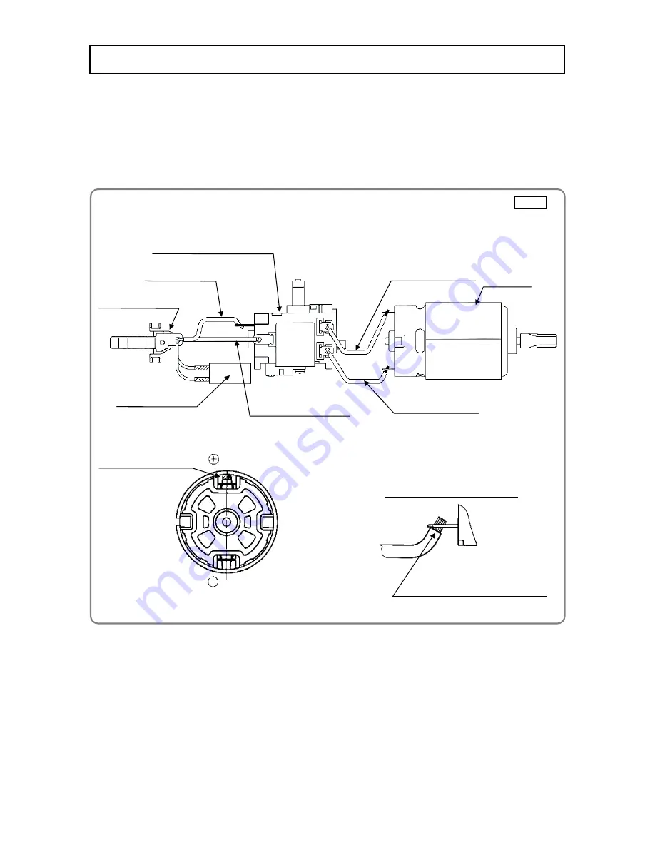
Red marking
(Indicate positive side)
Soldering of the internal wires
Apply solder to the inside of the
internal wire coating.
Motor
[28]
Battery Terminal
[37]
DC-Speed Control Switch
[35]
Internal Wire (Black)
[29]
Internal Wire (Red)
[34]
Noise Suppressor
[39]
Internal Wire (Black)
[38]
Internal Wire (Red)
[34]
• Soldering the internal wires to the Battery Terminal
[37]
and the DC-Speed Control Switch
[35]
Fig. 2
• Soldering the internal wires to the DC-Speed Control Switch
[35]
and the Motor
[28]
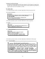
Reassembly can be accomplished by following the disassembly procedures in reverse. However, special
attention should be given to the following items.
1. Reassembly of the power supply unit
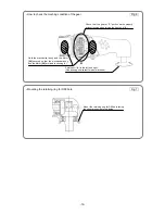
(1) Pay attention to the polarity of the Motor
[28]
and the soldering direction of the internal wires when
soldering the internal wires to the Battery Terminal
[37]
, Motor
[28]
and DC-Speed Control Switch
[35]
.
The red-marked side of the Motor
[28]
is positive.
(2) Mounting the Battery Terminal
[37]
, DC-Speed Control Switch
[35]
and Motor
[28]
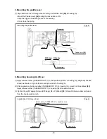
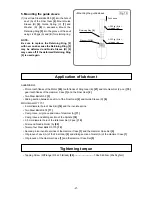
Connect the internal wires (red and black) of the controller as shown in Fig. 2 so that the internal wire
(red) does not contact the motor shaft and the internal wire (black) is not placed on the boss rib seat of
the pushing button.
Reassembly

