background image

--- 22 ---

(1) Voltage of battery

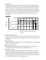
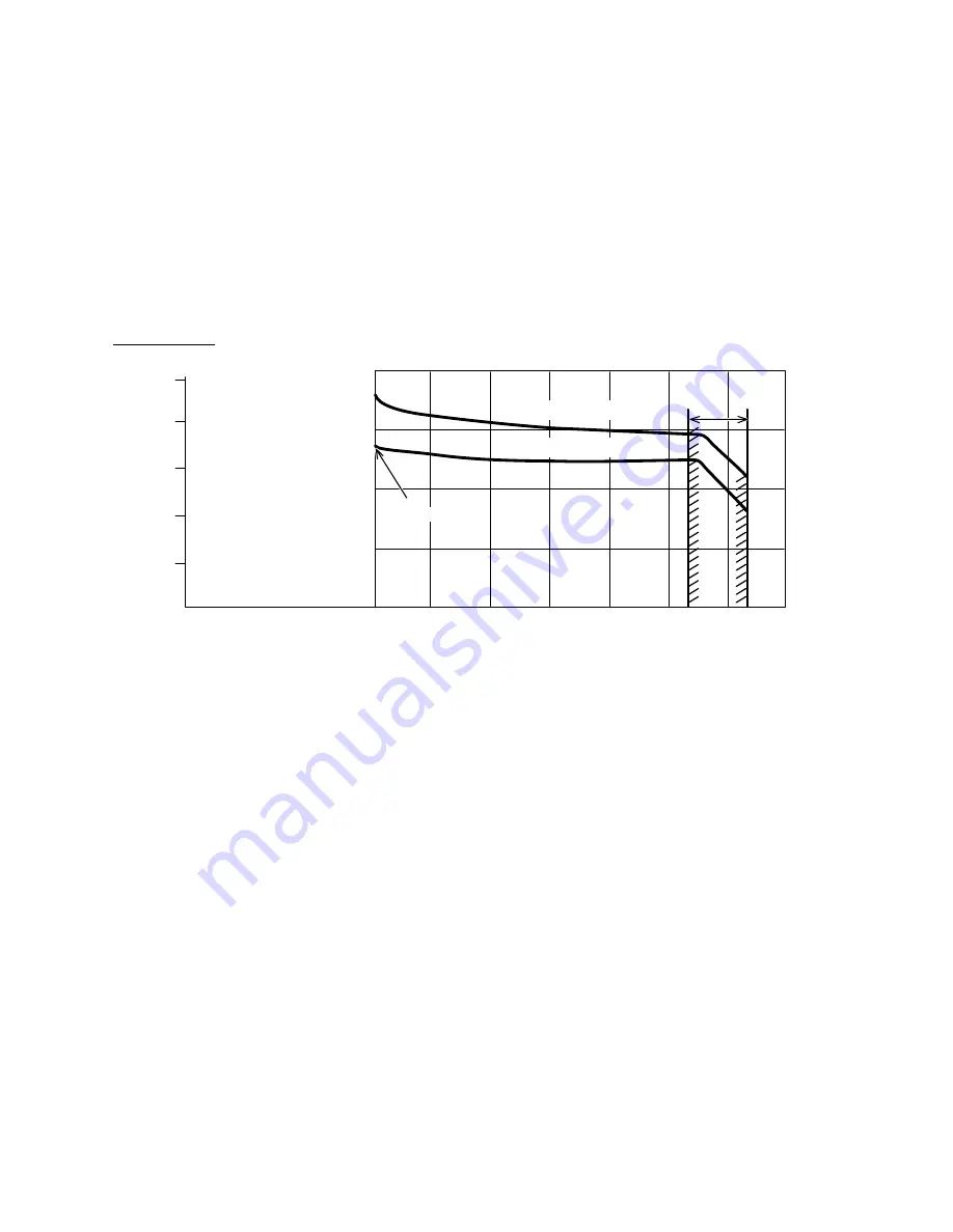
Tightening torque is affected by the voltage output of the battery.  For example, the relationship between

tightening torque and the number of M12 x 45 mm (15/32" x 1-3/4") high-strength bolts tightened is shown in

Fig. 8 below.  As can be seen in the graph, tightening torque decreases as the number of bolts tightened

increases.  This phenomenon is caused by the decline in voltage output of the battery due to the increasing

number of bolts tightened.  In particular, the tightening torque decreases rapidly just before the battery is fully

discharged (range "a" in the graph).  As this phenomenon is an inherent drawback in any cordless impact

driver, salespersons are requested to ensure that the customer is fully aware of and understands this

characteristic.

Model WR 8DH

Fig. 8

(2) Effects of low ambient temperatures

The tightening torque required may be reduced at low ambient temperatures or under the influence of grease

and different torque coefficients (dependent on manufacturing and finishing processes, and specified by bolt

manufacturers).

(3) Different bolt diameter

Differences in bolt diameter will cause variation of the required levels of tightening torque.  Generally speaking,

tightening torque is higher for large bolts.

(4) Different materials being tightened

When a bolt is tightened into a soft material such as aluminum, plastic, wood, etc., the tightening torque is

considerably less than when the bolt is tightened into a hard material such as steel.

(5) Different tightening conditions

The tightening torque may vary in accordance with bolt torque coefficient (dependent on manufacturing

process, and specified by bolt manufactures), bolt grade and bolt length, even though the dimensions of the

bolts are the same.  Tightening torque may also vary depending on the surface finishing state of tightening

materials (steel, aluminum, etc.), and materials to be tightened.  In addition, if there is seal packing, clearance,

etc., between tightening materials, the tightening torque is decreased.

Fully charged

a

Battery voltage

Tightening torque

M12 x 45 mm (15/32" x 1-3/4") high-strength bolt (tightening time: 3 seconds)

400

(39.2 N

m, 29 ft-lbs)

800

(78.4 N

m, 58 ft-lbs)

1,200

(117.6 N

m, 86 ft-lbs)

0

2

4

6

8

10

20

40

60

80

100

120

Number of screws driven per charge (EB 9B battery)

Tightening torque

Batter

y v

oltage

(pcs.)

(kgf

cm)

(V)

Summary of Contents for WH 8DH

Page 1: ...DATA AND SERVICE MANUAL CORDLESS IMPACT DRIVER WH 8DH CORDLESS IMPACT WRENCH WR 8DH SPECIFICATIONS AND PARTS ARE SUBJECT TO CHANGE FOR IMPROVEMENT LIST Nos WH 8DH F832 WR 8DH F833 Jul 1999 W MODEL WH 8DH WH 8DH WR 8DH WR 8DH ...

Page 2: ...DATA AND SERVICE MANUAL a symbol s is are used in the place of company name s and model name s of our competitor s The symbol s utilized here is are as follows Symbol Utilized Competitor Company Name Model Name C MAKITA 6908DWA WH 8DH ...

Page 3: ...e 12 6 4 Tightening Speed 16 6 5 Number of Screws or Bolts Driven 17 7 PRECAUTIONS IN SALES PROMOTION 19 7 1 Safety Instructions 19 7 2 Tightening Torque Inspection Prior to Operation 21 7 3 Tightening Torque Variation 21 7 4 Suggestions and precautions for the Efficient Use of the Charger 23 8 OTHER PRECAUTIONS 24 Service section 9 REPAIR GUIDE 25 9 1 Precautions in Disassembly and Reassembly 25 ...

Page 4: ...ally available 1 2 sockets The construction of the Model WR 8DH is the same as that of the Model WH 8DH except the anvil K assembly and the hammer case 3 APPLICATIONS Tightening loosening of small screws tapping screws wood screws bolts nuts etc Drilling into wood and various other materials with use of optional accessory drill chuck adapter Applicable Markets Wood product assembly Tightening loos...

Page 5: ...r motor life High power fan cooled DC magnet motor Higher heat resistance The same torque and speed in both forward and reverse modes Longer service life DC 9 6 V battery EB 9B or EB 9H Heavy duty aluminum hammer case Variable speed switch with electric brake Easy to use forward reverse changeover pushing button Ergonomically designed handle for a comfortable grip Grip inserts front and rear ...

Page 6: ...d DC magnet motor Higher heat resistance The same torque and speed in both forward and reverse modes Longer service life DC 9 6 V battery EB 9B or EB 9H Heavy duty aluminum hammer case Variable speed switch with electric brake Easy to use forward reverse changeover pushing button Ergonomically designed handle for a comfortable grip 12 7 mm 1 2 Square drive Grip inserts front and rear ...

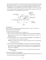
Page 7: ...ng its size by about 70 volume compared to our previous model 3 Construction of replaceable carbon brushes The carbon brush can be easily removed from the motor with a flat blade screwdriver as shown in Fig 2 and can also be easily and securely mounted to the motor by hanging the claw of the carbon brush on the connecting portion on the outside of the brush tube Claw of carbon brush Collar of carb...

Page 8: ...y 2 0 Ah 180 mm 7 1 8 x 220 mm 8 21 32 Battery Type EB 9H Sealed cylindrical nickel metal hydride batteries Nominal voltage DC 9 6V Nominal life Charging discharging approximately 500 cycles in case of Model UC 14YF2 Nominal capacity 2 2 Ah 1 In the case of tapping screws and wood screws a minimum of M3 1 8 is possible 2 This torque is based on tightening an M12 15 32 bolt strength grade 12 9 for ...

Page 9: ...ssories 1 Optional accessories for the Model WH 8DH Plus driver bit 50 mm 2 Bit No No 2 No 3 Code No 992671 992672 Hexagon socket L B Stamped figures 996177 8 5 16 65 2 9 16 8 Stamped figures 5 mm Hexagon socket Part Name L mm B mm Code No 985329 10 3 8 65 2 9 16 10 6 mm Hexagon socket 996178 12 15 32 65 2 9 16 12 5 16 Hexagon socket 996179 13 1 2 65 2 9 16 13 8 mm Hexagon socket 996180 14 9 16 65...

Page 10: ...16 32 1 1 4 34 1 11 32 36 1 13 32 40 1 9 16 B B B B C C D D 10 3 8 12 15 32 13 1 2 14 9 16 17 21 32 19 23 32 21 53 64 22 7 8 W 5 16 W 3 8 W 7 16 W 1 2 M 8 5 16 M 10 3 8 M 12 15 32 M 14 9 16 M 16 5 8 M 6 1 4 M 8 5 16 M 10 3 8 M 12 15 32 M 14 9 16 M 12 15 32 944291 873632 873539 873540 873536 873624 873626 873627 10 mm 12 mm 13 mm 14 mm 17 mm 19 mm 21 mm 22 mm Hexagon socket 12 7 mm 1 2 Square drive...

Page 11: ...955144 12 mm 13 mm 14 mm 17 mm 17 mm 19 mm 19 mm 21 mm 21 mm 21 mm 22 mm Long socket 12 7 mm 1 2 Square drive dimension Sq Part Name Code No Nominal diameter of applicable bolts Dihedral width H mm Shape Socket primary dimensions mm ISO high strength ISO ordinary ISO small type Inch screw L L1 D1 Bit adaptor Code No 991476 6 35 mm 1 4 45 mm 1 25 32 13 5 mm dia 17 32 12 7 mm 1 2 34 1 11 32 34 1 11 ...

Page 12: ... 307824 Use the holster to hold the unit during its operation Carefully read the warnings attached to the holster for safe use Hook Code No 308090 Use the hook to hold the unit during its operation Carefully read the instructions that come with the hook to learn how to use it ...

Page 13: ... 5 3 3 lbs Main body weight kg 67 66 68 No load sound pressure level dB A Driver chuck Driver chuck Driver chuck Tool tip mounting system Trigger switch with forward reverse changeover pushing button with brake and variable Type of switch Trigger switch with forward reverse changeover pushing button with brake Variable speed switch with forward reverse changeover lever DC magnet DC magnet DC magne...

Page 14: ... pushing button with brake and variable Type of switch DC magnet Type of motor 9 6 Voltage 20 Current EB 9B or EB 9H Battery V A Type EB 9B 2 0 EB 9H 2 2 Nominal capacity Ah 9 6 Nominal voltage V 0 40 Ambient temperature C UC 14YF2 Model 44 Power input capacity VA 7 2 14 4 Recharging voltage V Plastic tool case Charger UC 14YF2 Standard accessories Charger 1 Max tightening torque is based on tight...

Page 15: ... figures below are intended for reference purposes only 1 Impact Driver Fig 4 1 Fig 4 2 Test conditions Bolt M12 x 45 mm 15 32 x 1 3 4 M10 x 30 3 8 x 1 3 16 strength grade 12 9 Steel plate Mild steel M12 15 32 Thickness 25 mm 1 M10 3 8 Thickness 10 mm 3 8 Accessory tool Hexagon socket ass y An M10 x 30 high strength bolts are tested unless otherwise specified WH 8DH M12 x 45 WH 8DH WH 8DA2 200 19 ...

Page 16: ...he thread mm2 Strength grade and rated axial stress of threads Strength grade Rated axial stress kgf mm2 Material Heat treatment 4 8 6 8 8 8 12 9 29 1 43 7 58 2 95 Mild steel Alloy steel including Ni Mn Cr etc None Processed hard material Diameter and effective sectional areas of threads Kind of thread x pitch Effective sectional area of thread mm2 M5 x 0 8 mm 3 16 14 2 M6 x 1 mm 1 4 20 1 M8 x 1 2...

Page 17: ...3 3 Bolt Tightening Torque Characteristics Figs 6 1 and 6 2 show relationships between time and tightening torque for individual bolt types and sizes While the data are useful for handy reference actual tightening torque will vary depending on tightening conditions and other variables For details please refer to Para 7 3 Tightening Torque Variation Note The term tightening time indicates the impac...

Page 18: ...s 600 58 8 N m 43 ft lbs 800 78 4 N m 58 ft lbs 1000 98 N m 72 ft lbs 1200 117 6 N m 86 ft lbs kgf cm Tightening time steel plate thickness t 1 25 mm M12 x 45 mm 15 32 x 1 3 4 Tightening torque High strenge bolt Ordinary bolt 200 19 6 N m 14 ft lbs 0 1 2 3 400 39 2 N m 29 ft lbs 600 58 8 N m 43 ft lbs 800 78 4 N m 58 ft lbs 1000 98 N m 72 ft lbs 1200 117 6 N m 86 ft lbs kgf cm Tightening time stee...

Page 19: ...e sec Wood screw 4 2 mm dia x 90 mm length hemlock spruce HITACHI WH 8DH HITACHI WH 8DA2 C 5 9 sec Model 5 10 sec 6 5 sec 6 8 sec HITACHI WH 8DH HITACHI WH 8DA2 C 3 0 sec Model 1 sec 3 3 sec 3 5 sec 2 3 4 5 HITACHI WH 8DH HITACHI WH 8DA2 C 3 2 sec Model 1 sec 3 5 sec 3 8 sec 2 3 4 5 HITACHI WH 8DH HITACHI WH 8DA2 C 6 9 sec Model 5 10 sec 8 5 sec 8 7 sec 2 Tightening time sec Wood screw 4 2 mm dia ...

Page 20: ...the tables below Please note that the data below are intended for general reference only as the number of screws which can be tightened per charge will vary slightly depending on screw tightening conditions screw sizes ambient temperatures and the charging capacity of the battery 1 Number of screws or bolts driven Cordless impact driver Battery Tightening condition Model HITACHI WH 8DH HITACHI WH ...

Page 21: ...n to the completion As it can be seen when the tightening time is prolonged the number of screws which can be tightened per charge is decreased Please note that the left data are intended for general reference only as the number of screws which can be tightened per charge will vary slightly depending on screw tightening conditions screw sizes ambient temperatures and the charging capacity of the b...

Page 22: ... on the unit If this order is reversed the charger may not function properly 4 Ensure the power source voltage is the same as that indicated on the Name Plate of the charger Use of any other power source DC outlet fuel powered generator etc will cause the charger to overheat and burn out 5 Do not use any voltage increasing equipment transformer etc between the power source and the charger If the c...

Page 23: ...let or authorized service center when they are no longer capable of being recharged or repaired If thrown into a fire the batteries may explode or if discarded indiscriminately leakage of the cadmium compound contained in the battery may cause environmental pollution B Caution Plates 1 The following precautions are listed on the Name Plate attached to the main body of each tool For Europe ACHTUNG ...

Page 24: ...ening time is prolonged for such bolts and screws it could cause damage to their threads or in the worst case cause them to be sheared off This phenomenon is common to all existing impact drivers Particularly when tightening M6 1 4 or smaller screws tightening time must be kept extremely short 0 5 seconds or less The customer should be advised to carry out several screw tightening operations and a...

Page 25: ... 3 Different bolt diameter Differences in bolt diameter will cause variation of the required levels of tightening torque Generally speaking tightening torque is higher for large bolts 4 Different materials being tightened When a bolt is tightened into a soft material such as aluminum plastic wood etc the tightening torque is considerably less than when the bolt is tightened into a hard material su...

Page 26: ...the Efficient Use of the Charger 1 Batteries may not be rechargeable immediately after use If the Type EB 9B or EB 9H Storage Batteries are exposed to direct sunshine for an extended period or if the temperature of the batteries is 40 C 104 F or higher immediately after they have been used in the tool the pilot lamp may not light up when the batteries are connected to the Model UC 14YF2 Charger Th...

Page 27: ...orque but could also easily cause damage to the socket Please refer to the tables in Para 5 2 for appropriate socket dimensions 3 Hammering section lubrication Grease ATTOLUB MS No 2 is utilized in the hammering section Frequent or continuous use of the tool will cause excessive temperature rise of the hammering section resulting in depletion of the grease and subsequent increased wear of componen...

Page 28: ...ng A B Set 28 26 2 Removal of Housing B Remove the seven Tapping Screws D4 x 20 26 24 from the main body to remove Housing B 3 Remove the DC Speed Control Switch 30 28 Fin Ass y 32 30 Motor 23 21 Grip F 33 31 and Grip R 37 35 together Remove the Pushing Button 31 29 and the Strap 35 33 4 Disassembly of the switch ass y Remove the two Machine Screws M3 x 5 29 27 that secure the flag terminal and th...

Page 29: ...t is free The Guide Sleeve 4 can not be removed Avoid quickly raising the retaining ring or it may fly out forcefully The retaining ring can also be easily removed by widening the gap of the retaining ring with the jig for retaining ring and slowly raising the retaining ring with a small flat blade screwdriver 6 Disassembly of the hammer assembly Hammer 10 7 Push down Spindle 15 13 Spring 12 10 St...

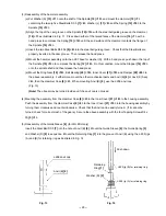
Page 30: ... proper wiring b When connecting the internal wires of the Motor 23 21 to the DC Speed Control Switch 30 28 tightly fasten them with the Machine Screw M3 x 5 29 27 paying close attention to the direction of the flag terminal Fig 12 2 c Mount the Motor 23 21 into Housing A so that the Brush Caps 25 23 of the Motor 23 21 and the rib for preventing motor body from rotating fit in Housing A Note Make ...

Page 31: ...urple Motor Pinion Black Purple Fin Ass y 32 30 FET S Tight Screw D3 5 x 6 36 34 Flag terminal Machine screw M3 x 5 29 27 DC Speed Control Switch 30 28 Projection of forward reverse lever Internal wire black Schematic diagram viewed from A ...

Page 32: ...Gear 18 16 Ball Bearing 20 18 Inner Cover 21 19 and Damper 22 20 to the above reassembly Furthermore mount the other mechanical parts and Anvil B 8 or Anvil K Ass y 4 then the Hammer Case 6 2 When mounting Anvil B 8 use the J 296 anvil cap Fig 13 Note The oil seal may be turned inside out if the anvil cap is not used 4 Mounting the assembly from the Hammer Case 6 2 to the Inner Cover 21 19 to the ...

Page 33: ...the metal Two Steel Balls D5 556 9 6 Pinion tooth flanks of the Motor 23 21 Tooth flanks of the Ring Gear 18 16 Twenty five Steel Balls D3 5 7 8 b HITACHI MOTOR GREASE No 29 for WH 8DH only Steel Ball D3 5 7 Sliding section of Anvil B 8 and the Guide Sleeve 4 8 Screw tightening torque Tapping Screw with sp washer D4 x 30 20 5 kgf cm 1 96 0 49 N m 1 44 0 36 ft lbs Tapping Screw with flange D4 x 20 ...

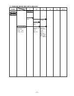
Page 34: ... 40 50 60 min Fixed Variable WH 8DH Work Flow Inner Cover Motor Switch Hammer Case Washer Anvil Ring Gear Housing General Assembly WR 8DH Steel Ball Hammer Ass y Spring Spindle Idle Gear Needle Roller Ball Bearing 6001C2 Fixed Cost Switch 0 min Others 20 min ...

Page 35: ... 32 Assembly Diagram for WH 8DH ...

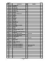
Page 36: ...5 WASHER C 1 20 600 1VV BALL BEARING 6001VVCMPS2L 1 21 316 167 INNER COVER 1 22 310 319 DAMPER 1 23 316 782 MOTOR 1 24 999 054 CARBON BRUSH 5X6X11 5 1 PAIR 2 25 316 180 BRUSH CAP 2 26 302 086 TAPPING SCREW W FLANGE D4X20 BLACK 7 27 NAME PLATE 1 28 317 879 HOUSING A B SET GREEN 1 INCLUD 33 37 29 994 532 MACHINE SCREW W SP WASHER M3X5 2 30 316 783 DC SPEED CONTROL SWITCH 1 31 316 166 PUSHING BUTTON ...

Page 37: ...IC HEX SOCKET 10MM 65L 1 606 996 178 NON MAGNETIC HEX SOCKET 12MM 65L 1 607 996 179 NON MAGNETIC HEX SOCKET 13MM 65L 1 608 996 180 NON MAGNETIC HEX SOCKET 14MM 65L 1 609 996 181 NON MAGNETIC HEX SOCKET 16MM 65L 1 610 996 182 NON MAGNETIC HEX SOCKET 17MM 65L 1 611 996 185 NON MAGNETIC HEX SOCKET 15MM 65L 1 612 996 186 NON MAGNETIC HEX SOCKET 19MM 65L 1 613 996 197 HEX SOCKET LONG 21MMX166L 1 614 99...

Page 38: ... 35 Assembly Diagram for WR 8DH ...

Page 39: ... WASHER C 1 18 600 1VV BALL BEARING 6001VVCMPS2L 1 19 316 167 INNER COVER 1 20 310 319 DAMPER 1 21 316 782 MOTOR 1 22 999 054 CARBON BRUSH 5X6X11 5 1 PAIR 2 23 316 180 BRUSH CAP 2 24 302 086 TAPPING SCREW W FLANGE D4X20 BLACK 7 25 NAME PLATE 1 26 317 879 HOUSING A B SET GREEN 1 INCLUD 31 35 27 994 532 MACHINE SCREW W SP WASHER M3X5 2 28 316 783 DC SPEED CONTROL SWITCH 1 29 316 166 PUSHING BUTTON 1...

Page 40: ...0 948 227 RETAINING RING FOR D47 HOLE 1 611 955 307 PINION 1 612 955 308 SLEEVE 1 613 955 309 WASHER 1 614 955 310 SOCKET COVER 1 615 955 311 SOCKET 1 616 303 247 SEAL LOCK HEX SOCKET HD BOLT M5X25 6 617 873 537 SOCKET PIN 1 618 873 187 O RING J1SW1516 1 619 991 481 FORM TIE SOCKET ASS Y 11 3MMX95L 1 INCLUD 617 618 620 944 291 HEX SOCKET ASS Y 10MMX40L 1 INCLUD 617 618 621 873 632 HEX SOCKET ASS Y...

Page 41: ...X SOCKET ASS Y LONG 21MMX75L 1 INCLUD 617 618 638 991 480 HEX SOCKET ASS Y LONG 21MMX125L 1 INCLUD 617 618 639 955 144 HEX SOCKET ASS Y LONG 22MMX52L 1 INCLUD 617 618 640 873 633 EXTENSION BAR ASS Y SQUARE 12 7MMX100L 1 INCLUD 617 618 641 992 610 UNIVERSAL JOINT ASS Y 1 INCLUD 617 618 642 642 955 153 UNIVERSAL JOINT PIN 1 643 993 658 SOCKET ASS Y FOR DUCT 12MMX95L 1 INCLUD 617 618 644 644 993 659 ...

Reviews: