--- 26 ---
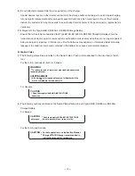
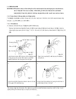
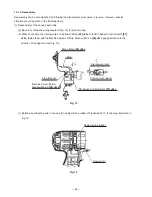
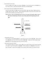
(6) Removal of the Carbon Brushes 5 x 6 x 11.5 (1 Pair)
[31] <26>
Remove the two Brush Caps
[32] <27>
. Catch the flanges of the Carbon Brushes 5 x 6 x 11.5 (1 Pair)
[31]
<26>
with a small flat-blade screwdriver and remove the Carbon Brushes 5 x 6 x 11.5 (1 Pair)
[31] <26>
at
both sides.
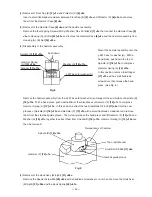
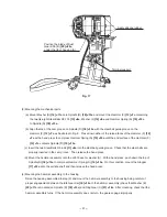
(7) Removal of housing (B)
Remove the seven Tapping Screws (W/Flange) D4 x 20 (Black)
[33] <28>
and the Machine Screw
(W/Washers) M4 x 25 (Black)
[47] <42>
from the main body. The Strap (Black)
[45] <40>
and Sleeve (A)
[46]
<41>
can be removed by removing the Machine Screw (W/Washers) M4 x 25 (Black)
[47] <42>
. Before
removing housing (B), be sure to remove the Brush Caps
[32] <27>
because housing (B) cannot be removed
if the Brush Caps
[32] <27>
are mounted.
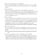
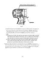
(8) Removal of the switch
The FET of the DC-Speed Control Switch
[37] <32>
is firmly inserted in the housing. Insert a small flat-blade
screwdriver between the FET and housing (B) to raise and remove the FET. Be careful not to break the three
legs coming from the FET to avoid malfunction of the switch. Then, Inner Cover (A)
[25] <20>
, Armature Ass'y
(W/Ball Bearing) DC 9.6 V
[26] <21>
, Magnet (E)
[28] <23>
, Brush Block
[30] <25>
and DC-Speed Control
Switch
[37] <32>
can be removed in a piece. Pushing Button (A)
[38] <33>
can also be removed.
NOTE: Be careful not to break the three legs coming from the FET to avoid malfunction of the switch.
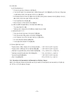
(9) Removal of the switch assembly
Remove the two Machine Screws (W/Sp. Washer) M3 x 5
[36] <31>
that secure the flag terminal and then
disconnect the internal wires (red and black) of the Brush Block
[30] <25>
from the DC-Speed Control Switch
[37] <32>
.
NOTE: Do not disconnect the three FET internal wires soldered to the DC-Speed Control Switch [37]
<32>.
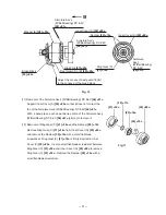
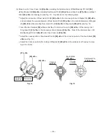
(10) Removal of Magnet (E)
[28] <23>
, Dust Guard Fin (B)
[29] <24>
and Side Yoke
[27] <22>
Magnet (E)
[28] <23>
has a strong magnetism. Pull Magnet (E)
[28] <23>
in the "B" direction (see Fig. 10)
holding Inner Cover (A)
[25] <20>
securely to remove it. Dust Guard Fin (B)
[29] <24>
and the Side Yoke
[27] <22>
can be easily removed from Magnet (E)
[28] <23>
by holding Magnet (E)
[28] <23>
securely and
pulling them in the direction of diameter because they are mounted to Magnet (E)
[28] <23>
magnetically.


