background image

Printed in Japan (H)

SM-E265 1109

Designed for excellent performance and user friendliness

Pursuing the Ideal Compact Inverter

Series

Pursuing the Ideal Compact Inverter

Hitachi Solar Water Pump 

Inverter System 

Summary of Contents for WJ-0001S

Page 1: ...Designed for excellent performance and user friendliness Pursuing the Ideal Compact Inverter Series Pursuing the Ideal Compact Inverter Hitachi Solar Water Pump Inverter System ...

Page 2: ...Hitachi Solar Water Pump Inverter System KHKSCO GROUP ...

Page 3: ...user for proper installation and for putting the system into use Scope Statement The scope of this manual covers only installation commissioning and general operations of the Solar Water Pump Inverter How ever some information on primary maintenance can be found in this manual ...

Page 4: ...ystem 4 Power Wire For Solar Inverter 4 1 Control Wiring For Solar Inverter 2 8 2 9 Keypad Description 2 10 Key and Indicator Legend 2 11 Operating Principle And Hardware 5 Principle of Solar Water Pump Inverter 5 1 MPPT Over view 5 2 Motor Requirement 5 3 System Start Up 6 Parameter Settings 6 1 Steps for setting Inverter for System 6 4 Fault Code 6 5 Monitoring System Data 6 6 PC Tools for Monit...

Page 5: ...About the System 1 In this chapter Page About the System Over View 1 1 Solar Power and Irrigation 1 1 ...

Page 6: ...uch difference in the daily lives as pumping water By providing water for irrigation or potable water have obvious benefits for people in rural areas and especially for those in developing nations The proper choice is determined by application specific factors like how much water is required and whether the water should be available at night or just during high sun hours Solar Power and Irrigation...

Page 7: ...Safety 2 In this chapter Page Introduction 2 1 Definition and Symbol 2 3 General warning and Cautions 2 3 UL Cautions Warning and Instructions ...

Page 8: ...e personnel familiar with the construction and operation of the equipment and the hazards involved Failure to observe this precaution could result in bodily injury WARNING For equipment protection install a ground leakage type breaker with a fast response circuit capable of handling large currents The ground fault protection circuit is not designed to protect against personal injury WARNING HAZARD...

Page 9: ...formed only by qualified personnel CAUTION b Any motor used must be of a suitable rating c Motors may have hazardous moving path In this event suitable protection must be provided CAUTION Hazardous main terminals for any interconnection motor contact breaker filter etc must be inaccessible in the final installation CAUTION This equipment should be installed in IP54 or equivalent enclosure CAUTION ...

Page 10: ...in this section summarizes the procedures necessary to ensure an inverter installation complies with delines 001L 002L 004L 007L 015S 022S 004H 007H 015H 022H and 030H WARNING Use 75 001S 002S 004S 007S 015L 022L 037L 055L 075L 110L 150L 040H 055H 075H 110H and 150H WARNING Suitable for use on a circuit capable of delivering not more than 100 000 rms Symmetrical Amperes 240 or 480V maximum WARNING...

Page 11: ...Installation Preparation 3 And Requirements In this chapter Page Installation Preparation 3 1 Mounting Location 2 3 Electrical Wiring 2 3 ...

Page 12: ... 0001S M3 5 1 0 AWG16 1 3mm2 WJ 0002S WJ 007S M4 1 4 AWG14 2 1mm2 WJ 0015S M4 1 4 AWG12 3 3mm2 WJ 0022S M4 1 4 AWG10 5 3mm2 WJ 0004H WJ 0007H WJ 0015H M4 1 4 AWG16 1 3mm2 WJ 0022H WJ 0030H M4 1 4 AWG14 2 1mm2 WJ 0040H M4 1 4 AWG12 3 3mm2 WJ 0055H WJ 0075H M5 3 0 AWG10 5 3mm2 WJ 0110H WJ 0150H M6 5 9 to 8 8 AWG6 13mm2 ...

Page 13: ...002S Class J 10 A AIC 200 kA WJ 0004S Class J 10 A AIC 200 kA WJ 0007S Class J 15 A AIC 200 kA WJ 0015S Class J 15 A AIC 200 kA WJ 0022S Class J 20 A AIC 200 kA WJ 0004H Class J 10 A AIC 200 kA 20A MMS 32H 480V 40A or MMS 63H 480V 52A WJ 0007H Class J 10 A AIC 200 kA WJ 0015H Class J 10 A AIC 200 kA WJ 0022H Class J 10 A AIC 200 kA WJ 0030H Class J 15 A AIC 200 kA WJ 0040H Class J 15 A AIC 200 kA ...

Page 14: ...icular wall that is not subject to vibration Otherwise it may fall and cause injury to personnel CAUTION Be sure not to install or operate an inverter that is damaged or has missing parts Otherwise it may cause injury to personnel CAUTION Be sure to install the inverter in a well ventilated room that does not have direct exposure to sunlight a tendency for high temperature high humidity or dew con...

Page 15: ...to provide adequate ventilation Otherwise the inverter may overheat and cause equipment damage or fire Electrical Wiring You will connect wiring to the input of the inverter First you must determine whether the inverter model you have required three phase power only or single phase power only All models have the same power connection terminals R L1 S L2 and T L3 So you must refer to the specificat...

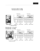
Page 16: ...Ii Single phase 200V 0 1 to 0 4kW Three phase 200V 0 1 to 0 75kW ...

Page 17: ...Ii ...

Page 18: ...Ii ...

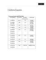
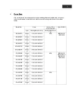
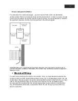
Page 19: ...Solar Water System 4 Wiring details ...

Page 20: ...Ii Connection to Solar Water Pump System DC PV Power AC Grid Power All Type Induction motor pump and PMAC motor Pump Hitachi Solar Water Pump Inverter Inverter Input Power AC DC Both ...

Page 21: ...Ii Power Wiring For Solar Power in Solar Water Pump Inverter DC Input SOLAR PV MODULE DC POWER DC Power Hitachi Solar Water Pump Inverter R S T U V W M E Water Submersible Pump AC and PMAC Motor ...

Page 22: ...e When AC Grid Power and DC PV Power use with change over switch Alternatively AC and DC power use in Inverter AC Grid Power SOLAR PV MODULE DC POWER AC DC Power Change Over Switch AC MCB DC Fuses Hitachi Solar Water Pump Inverter R S T U V W M E Water Submersible Pump AC and PMAC Motor Option ...

Page 23: ...er use together In Inverter Where DC PV Module Total Vmp Value should be higher than AC Grid Voltage x 1 414 AC Grid Power SOLAR PV MODULE DC POWER Switch AC MCB DC Fuses Hitachi Solar Water Pump Inverter R S T U V W M E Water Submersible Pump AC and PMAC Motor Fuses And Diodes For Reverse Polarity Protection Note ...

Page 24: ...ving Start command to pump and for above 15kw It is require to put start switch between P24 and FW terminal of Control board 2 Customer can use Push button for reset error of inverter for getting immediate restart command 3 There is delay restart timer inside inverter for error come while dark cloud or suddenly power changes in PV panel Like undervoltage For Rating above 15Kw SJ700D ...

Page 25: ... monitors etc 9 Run key Makes inverter run 10 Stop reset key Makes inverter decelerates to a stop Reset the inverter when it is in trip situation 11 ESC key Go to the top of next function group when a function mode is shown Cancel the setting and return to the function code when a data is shown Moves the cursor to a digit left when it is in digit to digit setting mode Pressing for 1 second leads t...

Page 26: ...and percentage RUN key enable LED Lights up when the inverter is ready to respond to the RUN key When this lamp is on you can start the inverter with the RUN key on the digital operator RUN key Starts the inverter to run the motor This key is effective only when the operating device is the digital operator To use this key confirm that the operating device indicator lamp is on STOP RESET key Decele...

Page 27: ...Operating Principle 5 And Hardware ...

Page 28: ...rter series specifically design for pump application which has special reduce torque control mode with energy saving technology It is design for meet requirement of pump manufacturer and OEM to customize application as per their requirements Control Mode Reduce Torque technology is mostly utilized in pump application where load on motor shaft have very high inertia momentum It operates on starting...

Page 29: ...ter is in stop command then PV cell generating short circuit current and if the PV cells are not connected to any load then output voltage of cell is same as open circuit voltage of PV See below I V characteristic The I V curve is not constant for all instant the intensity of sun ray and temperature changes during a day time The current changes linearly with Intensity and voltage change very small...

Page 30: ...System Start up 6 ...

Page 31: ... Stop Reset button use for stop motor form operator panel keypad and also to reset alarm ESC button use for going back to parameter group number Use for go out from parameters SET button use for going inside of parameter and setting change value of parameters in eeprom memory 1 UP arrow and 2 DOWN arrow button use for changing digit value Means change parameter number as well as value inside param...

Page 32: ...W Hz RPM Current Votlage A003 Hz of motor H003 KW of motor H004 Pole of motor which come from RPM of motor A002 01 Terminal Run command F002 100 Sec Acceleration Time F003 1 Sec Deceleration time A020 Put Total Vmp of connect PV cells C001 56 Terminal 1 as Forward Run command C006 18 Terminal 6 as Reset inverter P101 3 min Auto restart delay time after inverter get any alarm Change as per requirem...

Page 33: ...side of inverter like KW Hz RPM Current Votlage A003 Hz of motor H003 KW of motor H004 Pole of motor which come from RPM of motor A002 01 Terminal Run command F002 100 Sec Acceleration Time F003 1 Sec Deceleration time A020 Put Total Vmp of connect PV cells C001 56 Terminal 1 as Forward Run command C006 18 Terminal 6 as Reset inverter P101 3 min Auto restart delay time after inverter get any alarm...

Page 34: ...rrent Votlage A003 Hz of motor H003 KW of motor H004 Pole of motor which come from RPM of motor A002 01 Terminal Run command F002 100 Sec Acceleration Time F003 1 Sec Deceleration time A020 Put Total Vmp of connect PV cells C001 56 Terminal 1 as Forward Run command C006 18 Terminal 6 as Reset inverter P101 3 min Auto restart delay time after inverter get any alarm Change as per requirements P130 3...

Page 35: ...nergy from the motor E08 EEPROM error When the built in EEPROM memory has problems due to noise or excessive temperature the inverter trips and turns OFF its output to the motor E09 Under voltage error A decrease of internal DC bus voltage below a threshold results in a control circuit fault This condition can also generate excessive motor heat or cause low torque The inverter trips and turns OFF ...

Page 36: ...verter trips and turns OFF the output E36 Braking error When 01 has been specified for the Brake Control Enable b120 the inverter will trip if it cannot receive the braking confirmation signal within the Brake Wait Time for Confirmation b124 after the output of the brake release signal E37 Safe Stop Safe stop signal is given E38 Low speed overload protection If overload occurs during the motor ope...

Page 37: ...he mounted option board E69 Option error inverter communication error If timeout occurs during the communication between the inverter and DeviceNet option board the inverter will shut off its output and display the error code shown on the right E80 Encoder disconnection If the encoder wiring is disconnected an encoder connection error is detected the encoder fails or an encoder that does not suppo...

Page 38: ...work under Hitachi solar inverter 200VAC Hitachi inverter can work for 0VAC to 240VAC motor 400VAC Hitachi inverter can work for 0 VDC to 460VAC motor Motor should be three phase three wire input DC motor can t be work For PMDC motor Please contact concern Hitachi Person ...

Page 39: ...D102 DC voltage level at DC bus inside inverter D013 Output voltage to motor It may be less as per energy saving mode compare to V F ratio D014 input KW power consumption D015 Total KW power consume by inverter motor D016 Total Run time of motor in Hr D017 Total power on time of inverter in Hr D018 Heat sink temperature of inverter PC tool for monitoring ...

Page 40: ...9 to 8 8Nm Components Overheating Thermal trip events No trip events IGBT Resistance value Terminal block Secure connections Visual No abnormalities Smoothing capacitors Leaking swelling Visual No abnormalities Relay s Chattering Aural Single click when switching ON or OFF Resistors Cracks or discoloring Visual Check Ohms of optional braking res Control circuit Function Voltage balance between pha...

Page 41: ...re Note 2 Designed life of a cooling fan is 10 years However it is affected by the ambient temperature and other environmental conditions Note 3 The inverter must be cleaned periodically If dust accumulates on the fan and heat sink it can cause overheating of the inverter ...

Page 42: ...Network Communication 7 ...

Page 43: ...s Communication mode Asynchronous Character code Binary LSB placement Transmits LSB first Electrical interface RS 485 differential transceiver Data bits 8 bit Modbus RTU mode Parity None even odd Stop bits 1 or 2 bits Startup convention One way start from host device Wait time for response 0 to 1000 msec Connections Station address numbers from 1 to 32 Connector Terminal connector Error check Over...

Page 44: ...minal 02 Run key on keypad or digital operator 03 Modbus network input C071 Communication speed 05 03 2400 bps 04 4800 bps 05 9600 bps 06 19 2k bps 07 38 4k bps 08 57 6k bps 09 76 8k bps 10 115 2k bps C072 Modbus Address 1 Network address range is 1 to 247 C074 Communication parity 00 00 No parity 01 Even parity 02 Odd parity C075 Communication stop bit 1 Range is 1 or 2 C076 Communication error s...

Page 45: ...erter will show over voltage alarm then try to reduce PV qty in series Now Best selection as below for series and parallel connection Example If Pump motor voltage is 415VAC Then try to make Total Vmp value of connected near to 585 to 600VDC It should be 1 414 time of Pump motor voltage Fault If find E01 E02 E03 E04 and E05 during starting of pump Remedies Check following parameters F002 50 second...

Page 46: ...Application Notes FOR Best Vmpp value to set in A020 D004 VOC 1 2 OR D004 VOC VOC 1 25 PV in Series PV in Parallel Ii ...

Page 47: ... 4 3 9 4 9 CT 0 3 0 6 1 2 2 0 3 3 4 5 Input Rating Rated input voltage V 1 phase 200V 15 to 240V 10 50 60Hz 5 Rated input current A VT 2 0 3 6 7 3 13 8 20 2 24 0 CT 1 3 3 0 6 3 11 5 16 8 22 0 Output Rating Rated output voltage V 2 3 phase 200 to 240V proportional to input voltage Rated output current A VT 1 2 1 9 3 5 6 0 9 6 12 0 CT 1 0 1 6 3 0 5 0 8 0 11 0 Minimum value of resistor Ω 100 100 100 ...

Page 48: ...expired THM thermal warning BRK brake release BER brake error ZS 0Hz detection DSE speed deviation excessive POK positioning completion ODc analog voltage input disconnection OIDc analog current input disconnection FBV PID second stage output NDc network disconnect detection LOG1 LOG3 Logic output signals WAC capacitor life warning WAF cooling fan warning FR starting contact OHF heat sink overheat...

Reviews: