2.3 IMPORTANT NOTICE
• The supplementary information about the purchased
products is supplied in a CD-ROM, which can be found
bundled with the unit. In case that the CD-ROM is missing
or it is not readable, please contact your HITACHI dealer or
distributor.
•
PLEASE READ THE MANUAL AND THE FILES ON THE
CD-ROM CAREFULLY BEFORE STARTING TO WORK ON
THE INSTALLATION OF THE AIR TO WATER HEAT PUMP
SYSTEM.
Failure to observe the instructions for installation,
use and operation described in this documentation may
result in operating failure including potentially serious faults,
or even the destruction of the air to water heat pump system.
• Verify, in accordance with the manuals which appear in
the unit, that all the information required for the correct
installation of the system is included. If this is not the case,
contact your distributor.
• HITACHI pursues a policy of continuous improvement in
product design and performance. The right is therefore
reserved to vary specifications without notice.
• HITACHI cannot anticipate every possible circumstance that
might involve a potential hazard.
• This air to water heat pump has been designed for standard
water heating for human beings only. Do not use this for
other purposes such as for drying clothes, heating foods or
for any other heating process (except swimming pool).
• No part of this manual may be reproduced without written
permission.
• If you have any questions, contact your service contractor of
HITACHI.
• Check and make sure that the explanations of each part
of this manual correspond to your air to water heat pump
model.
•
Refer to the models codification to confirm the main
characteristics of your system.
• Signal words (NOTE, DANGER and CAUTION) are used
to identify levels of hazard seriousness. Definitions for
identifying hazard levels are provided in initial pages of this
document.
• The operation modes of these units are controlled by the unit
controller.
• This manual should be considered as a permanent part of
the air to water heat pump. It gives a common description
of and information for this air to water heat pump which you
operate as well as for other models.
• Keep the water temperature of the system above the
freezing temperature.
!
C A U T I O N
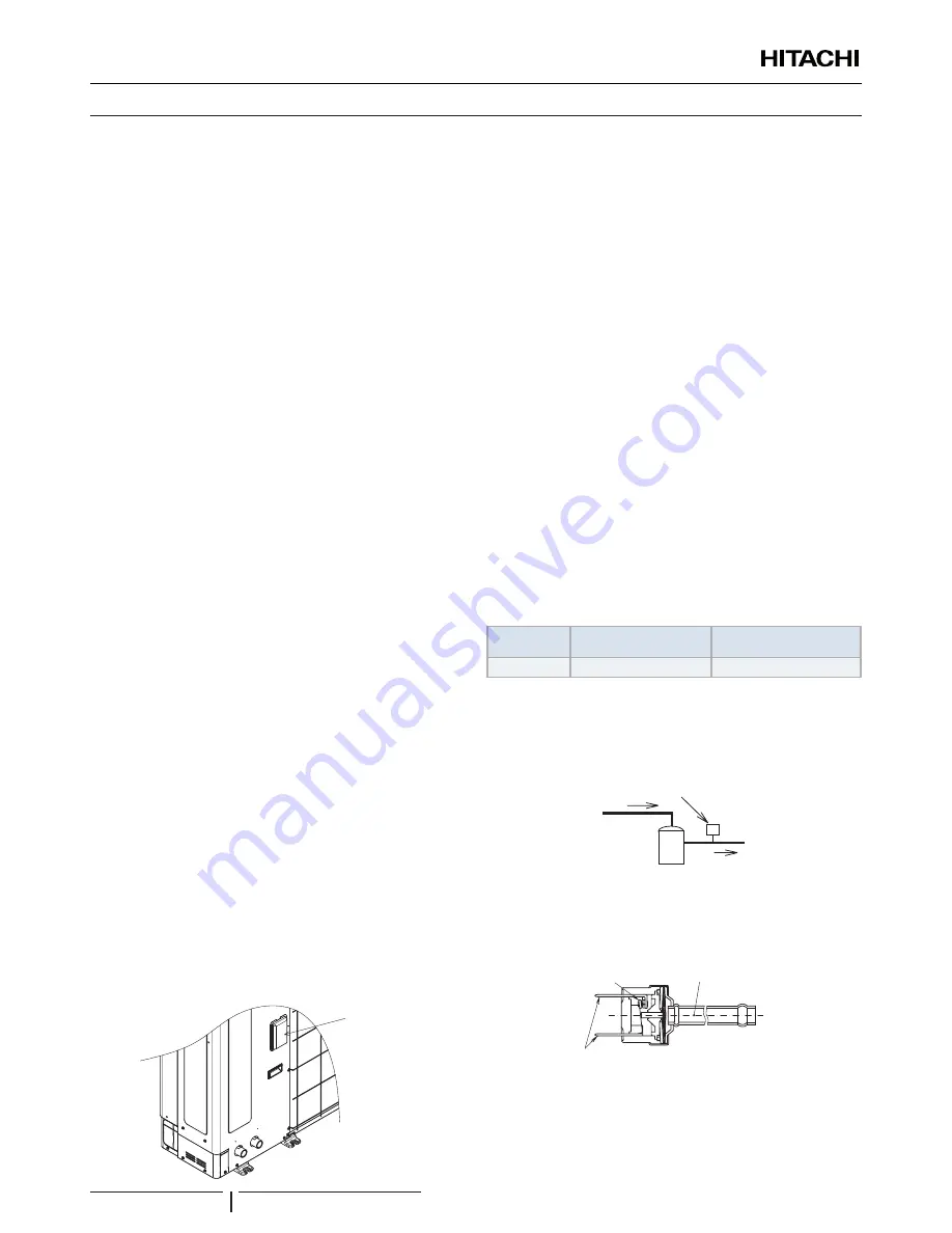
Do not pass cables through the ventilation hole.
Ventilation
hole
!
D A N G E R
Pressure Vessel and Safety Device: This heat pump is equipped
with a high pressure vessel under PED (Pressure Equipment
Directive). The pressure vessel has been designed and tested
before shipment according to PED. Also, in order to prevent the
system from an abnormal pressure, a high pressure switch, which
needs no field adjustment, is utilized in the refrigeration system.
Therefore, this heat pump is protected from abnormal pressures.
However, if abnormally high pressure is applied to the refrigeration
cycle including the high pressure vessel(s), it will result in serious
injury or death due to explosion of the pressure vessel. Do not apply
a pressure higher than the following pressure to the system, by
modifying or changing the high pressure switch.
!
C A U T I O N
This unit is designed for commercial and light industrial application.
If installed in house hold appliance, it could cause electromagnetic
interference.
Start-up and Operation:
Check to ensure that all the stop
valves are fully opened and no obstacle exists at the inlet/outlet
sides before start-up and during the operation.
Maintenance:
Periodically check the high pressure side
pressure. If the pressure is higher than the maximum allowable
pressure, stop the system and clean the heat exchanger or
remove the cause.
Maximum Allowable Pressure and High Pressure Cut-out
Value:
Refrigerant
Maximum Allowable
Pressure (MPa)
High Pressure Switch
Cut-out Value (MPa)
R410A
4.15
4.00 ~ 4.10
?
N O T E
The label for the vessel under PED are attached on the high pressure
vessel. The pressure vessel capacity and vessel category are indicated
on the vessel.
Location of High Pressure Switch
Compressor
?
N O T E
The high pressure switch is indicated on the electrical wiring diagram in
the outdoor unit as PSH connected to printed circuit board (PCB1) in the
outdoor unit
Structure of High Pressure Switch
Contact Point
Pressure Detected
Connected to the electrical wire
!
D A N G E R
• Do not change the high-pressure switch locally or change the
high pressure cut-out set value locally. If changed, it will cause
serious injury or death due to explosion.
• Do not attempt to turn service valve rod beyond its stop.
SAFETY
PMML0342B rev.1 - 03/2016
2


