ENGLISH
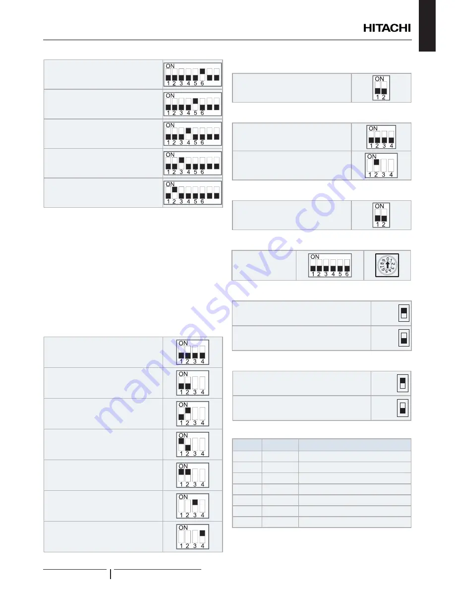
Unit and installation pipes antifreeze
protection
8
7
Standard / ECO water pump operation
8
7
Electric heater or boiler emergency mode
8
7
DHW tank’s heater operation
8
7
DHW 3-way valve forced ON
8
7
!
C A U T I O N
• Never turn all DSW4 dip switch pins ON. If this happens, the software
of the unit will be removed.
• Never activate “Heater Forced OFF” and “Electric heater or boiler
emergency mode” at the same time.
DSW5: Additional setting 3
In the cases where the outdoor unit is installed into a location
where its own outdoor ambient temperature sensor can not
give a suitable temperature measurement to the system, it
is available the 2nd outdoor ambient temperature sensor as
accessory. By means of DSW1&2 setting, the preferable sensor
for each circuit can be selected.
Factory setting
Outdoor unit sensor for circuits 1 and 2.
Outdoor unit sensor for circuit 1; Auxiliary
sensor for circuit 2.
Auxiliary sensor for circuit 1; Outdoor unit
sensor for circuit 2.
Auxiliary sensor instead of outdoor unit
sensor for both circuits.
4-20 mA setting temperature
(Only manual operation)
Use the maximum temperature value
between Two3 (boiler / heater thermistor) and
Two (water outlet thermistor) for water control
DSW6: Not used
Factory setting
(Do not change)
DSW7: Additional setting 4
Factory setting
Defrost for the water electric heater
DSW8/DSW18: Not used
Factory setting
(Do not change)
DSW15 & RSW2/ DSW16 & RSW1: Not used
Factory setting
(Do not change)
SSW1: Remote/Local
Factory setting
(Remote operation)
Remote
Local
Local operation
Remote
Local
SSW2: Heat/Cool
Factory setting
(Heat operation)
Heat
Cool
Cool and Heat operation in case of Local
Heat
Cool
9.5.4 LED indication
Name
Colour
Indication
LED1
Green
Power indication
LED2
Red
Power indication
LED3
Red
Heat pump operation (thermo ON/OFF)
LED4
Yellow
Alarm (flickering with 1 sec interval)
LED5
Green
Not used
LED6
Yellow
H-Link transmission
LED7
Yellow
H-Link transmission for unit controller
ELECTRICAL AND CONTROL SETTINGS
PMML0342B rev.1 - 03/2016
23


