


OPERATING THE MACHINE
5-4
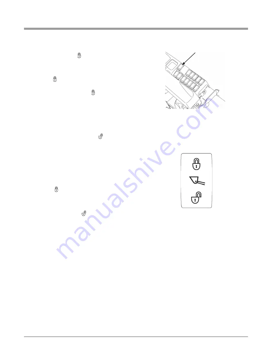
Control Lever Lock
d
WARNING:
Be sure to press lock ( ) side of control lever lock
switch (1).
Before leaving the operator's seat, be sure to stop
the engine. Then, set control lever lock switch (1) to
the lock ( ) position.
Always check to be sure that the control lever
lock switch is set in the lock ( ) position before
transporting the machine or leaving the machine at
the end of the shift.
Control lever lock switch (1) is provided to prevent
unexpected machine operation if the operator were to
mistakenly come in contact with the bucket and/or lift arm
control lever when getting on or off the machine. When
control lever lock (1) is placed in unlock ( ) position, the
control lever becomes operable.
Control Lever Lock Operation
When leaving the operator's seat:
1. Park the machine on solid level ground. Lower the
bucket to the ground. Return all levers to neutral. Set
the parking brake. Stop the engine.
2. Press lock ( ) side of control lever lock switch (1).
Before starting operation:
Before starting operation, check that control lever lock
switch (1) is in the unlock ( ) position.
Unlock
Lock
115MNEC-07-01
1
MNEC-01-015
Summary of Contents for ZW 550-6
Page 4: ......
Page 10: ...CONTENTS SPECIFICATIONS 12 1 Specifications 12 1 Intended Use 12 1 INDEX 14 1 ...
Page 12: ...MACHINE NUMBERS 2 Aftertreatment Device SCR TYPE MFG NO DOC TYPE MFG NO 95Z7B SCR4 95Z7B SCR4 ...
Page 54: ...SAFETY LABELS S 42 2 25 7 4 1 26 1 8 9 5 6 11 12 10 24 115Z7B S 42US ...
Page 148: ...OPERATOR S STATION 1 84 MEMO ...
Page 208: ...OPERATOR S STATION 1 144 MEMO ...
Page 210: ...BREAK IN 2 2 MEMO ...
Page 226: ...OPERATING THE ENGINE 3 16 MEMO ...
Page 274: ...OPERATING THE MACHINE 5 28 MEMO ...
Page 354: ...MAINTENANCE 7 70 MEMO ...
Page 418: ...9 4 MAINTENANCE UNDER SPECIAL ENVIRONMENTAL CONDITIONS MEMO ...
Page 422: ...10 4 STORAGE MEMO ...
Page 428: ...11 6 TROUBLESHOOTING MEMO ...
Page 430: ...SPECIFICATIONS 12 2 MEMO ...
Page 438: ...INDEX 14 8 ZW550 6 US MEMO ...


