MAINTENANCE
7-48
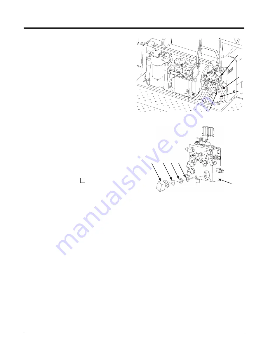
[ Line Filter in Brake Circuit ]
7. Place a suitable container under combination valve
(6).
8. Disconnect hoses (7, 8) and remove bolt (9).
d
WARNING: Be sure to wear safety glasses when
cleaning the air breather with compressed air.
9. Remove adapter (10) and filter (11) from the valve,
and clean filter (11) by applying air or cleaning
solution from the oil flow outlet side.
10. Install the cleaned filter (11) with washer (12) and
O-ring (13), and tighten adapter (10).
11. After replacing the return filter element, bleed air
from the hydraulic pump and check the oil level in
the hydraulic oil tank.
(Refer to the descriptions for “Bleed air from the
hydraulic system” in item
2
.)
d
CAUTION: If the machine is operated without
bleeding the air mixed in the hydraulic circuit,
damage to the hydraulic pump may result.
f
NOTE: Clean the filters at the regular intervals to
maintain clean hydraulic oil and extend the service life of
the hydraulic components.
115Z7B-7-45-2
6
11
12
13
10
MNHE-07-031
9
7
8
6
Summary of Contents for ZW 550-6
Page 4: ......
Page 10: ...CONTENTS SPECIFICATIONS 12 1 Specifications 12 1 Intended Use 12 1 INDEX 14 1 ...
Page 12: ...MACHINE NUMBERS 2 Aftertreatment Device SCR TYPE MFG NO DOC TYPE MFG NO 95Z7B SCR4 95Z7B SCR4 ...
Page 54: ...SAFETY LABELS S 42 2 25 7 4 1 26 1 8 9 5 6 11 12 10 24 115Z7B S 42US ...
Page 148: ...OPERATOR S STATION 1 84 MEMO ...
Page 208: ...OPERATOR S STATION 1 144 MEMO ...
Page 210: ...BREAK IN 2 2 MEMO ...
Page 226: ...OPERATING THE ENGINE 3 16 MEMO ...
Page 274: ...OPERATING THE MACHINE 5 28 MEMO ...
Page 354: ...MAINTENANCE 7 70 MEMO ...
Page 418: ...9 4 MAINTENANCE UNDER SPECIAL ENVIRONMENTAL CONDITIONS MEMO ...
Page 422: ...10 4 STORAGE MEMO ...
Page 428: ...11 6 TROUBLESHOOTING MEMO ...
Page 430: ...SPECIFICATIONS 12 2 MEMO ...
Page 438: ...INDEX 14 8 ZW550 6 US MEMO ...


