background image

Summary of Contents for ZW180

Page 1: ......

Page 2: ......

Page 3: ...aterial MANUAL COMPOSITION This manual consists of three portions the Techni cal Manual Operational Principle the Technical Manual Troubleshooting and the Workshop Man ual Information included in the Technical Manual Operational Principle technical information needed for redelivery and delivery operation and activation of all devices and systems Information included in the Technical Manual Trouble...

Page 4: ...T Indicates a situation which if not conformed to the instructions could result in damage to the machine NOTE Indicates supplementary technical information or know how UNITS USED SI Units International System of Units are used in this manual MKSA system units and English units are also indicated in parenthheses just behind SI units Example 24 5 MPa 250 kgf cm 2 3560 psi A table for conversion from...

Page 5: ...oup 4 Electrical System SECTION 3 COMPONENT OPERATION Group 1 Pump Device Group 2 Control Valve Group 3 Hydraulic Fan Motor Group 4 Steering Pilot Valve Group 5 Steering Valve Group 6 Pilot Valve Group 7 Charging Block Group 8 Ride Control Valve Group 9 Drive Unit Group 10 Axle Group 11 Brake Valve Group 12 Others TECHNICAL MANUAL Troubleshooting SECTION 4 OPERATIONAL PER FORMANCE TEST Group 1 Int...

Page 6: ...3 Hood Group 4 Center Hinge Group 5 Hydraulic Oil Tank Group 6 Pump Device Group 7 Control Valve Group 8 Pilot Valve Group 9 Pilot Shutoff Valve Group 10 Hydraulic Fan Motor SECTION 3 BASE MACHINE TRAVEL SYSTEM Group 1 Tire Group 2 Drive Unit Group 3 Axle Group 4 Propeller Shaft Group 5 Brake Valve Group 6 Charging Block Group 7 Steering Pilot Valve Group 8 Steering Valve Group 9 Steering Cylinder...

Page 7: ...ctrical System Overview T1 2 4 Electrical System In Cab T1 2 5 Engine and Fan Pump T1 2 10 Pump Device T1 2 11 Drive Unit T1 2 11 Control Valve T1 2 12 Ride Control Valve Optional T1 2 13 Charging Block T1 2 13 Fan Motor T1 2 13 Steering Valve T1 2 14 Emergency Steering Pump Optional T1 2 14 Group 3 Component Specifications Engine T1 3 1 Engine Accessories T1 3 5 Hydraulic Component T1 3 7 Electri...

Page 8: ...4GDT 1 2 Blank ...

Page 9: ... mm ft in 3280 10 9 D Wheel Base mm ft in 3050 10 0 E Tread mm ft in 2050 6 9 F Ground Clearance mm ft in 395 1 4 G Bucket Hinge Height mm ft in 3920 12 10 H Dumping Clearance 45 mm ft in 2800 9 2 I Dumping Reach 45 mm ft in 1070 3 6 R1 Minimum Rotation Radius Center of Outside Tire mm ft in 5230 17 2 R2 Minimum Rotation Radius Bucket Outside Edge mm ft in 6110 20 1 Travel Speed Forward Reverse km...

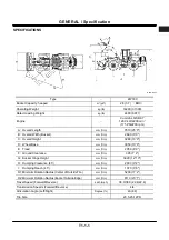
Page 10: ...GENERAL Specification T1 1 2 Blank ...

Page 11: ...ng Light 10 Lift Arm Cylinder 2 Bell Crank 5 Front Working Light 8 Rear Combination Light Turn Signal Hazard Light Clearance Light Brake Light and Back Light 11 Lift Arm 3 Bucket Cylinder 6 Rear Working Light Optional 9 Turn Signal Hazard Light and Clearance Light 12 Bucket Link 1 2 3 4 5 6 12 11 10 9 7 8 ...

Page 12: ... Oil Cooler 2 Pilot Valve 7 Stop Valve 12 Intercooler 17 Muffler 3 Brake Valve 8 Pilot Shut Off Valve 13 Torque Converter Cooler 18 Coolant Reservoir 4 Steering Pilot Valve 9 Pilot Filter 14 Fan Motor 19 Air Cleaner 5 Steering Valve 10 Engine 15 Radiator 20 Hydraulic Oil Tank 1 2 3 4 5 6 7 8 9 20 19 17 18 16 15 14 12 11 10 13 ...

Page 13: ...AIN COMPONENT LAYOUT TRAVEL SYSTEM T4GD 01 02 007 1 Front Axle 4 Pump Device 6 Rear Axle 8 Steering Accumulator 2 Propeller Shaft Front 5 Transmission 7 Propeller Shaft Rear 9 Brake Pressure Sensor 3 Steering Cylinder 1 2 3 4 5 6 8 7 9 ...

Page 14: ... 10 Lift Arm Proximity Switch 2 Air Filter Restriction Switch 5 Fuel Level Sensor 8 Lift Arm Angle Sensor Optional 11 Fresh Air Temperature Sensor 3 Reverse Buzzer 6 Hydraulic Oil Temperature Sensor 9 Bucket Proximity Switch 9 10 1 2 3 4 5 7 In Cab Refer to T1 2 5 Engine and Fan Pump Refer to T1 2 10 Pump Device Refer to T1 2 11 Drive Unit Refer to T1 2 11 8 11 6 ...

Page 15: ... IN CAB T4GB 01 02 006 1 Radio 3 Speaker 5 Brake Light Switch 6 Front Wiper Motor 2 Auxiliary Switch Panel Optional 4 Rear Wiper Motor 1 2 3 4 6 5 Monitor and Switches Refer to T1 2 8 Controller and Relays Refer to T1 2 6 Right Consol Refer to T1 2 7 ...

Page 16: ... Right A R8 27 Kick Out Relay B R10 4 ICF 12 Horn Relay A R5 20 Working Light Relay Rear A R7 28 Leveler Relay B R9 5 Dr ZX Connector 13 Brake Light Relay A R4 21 Working Light Relay Front A R6 29 Rear Washer Relay B R8 6 Fuse Box 14 High Beam Relay A R3 22 Back Buzzer Relay B R5 30 Rear Wiper Relay B R7 7 Auxiliary Relay 4 Used 15 Head Light Relay Right A R2 23 Neutral Relay B R4 31 Register Rela...

Page 17: ...ever 7 Quick Coupler Switch Optional 12 Fan Reversing Switch 16 Cigar Lighter 3 Lift Arm Control Lever 8 Lift Arm Auto Leveler Downward Set Switch Optional 13 Fog Light Switch Optional 17 DSS USS Down Shift Up Shift Switch 4 FNR Switch 9 Lift Arm Auto Leveler Upward Set Switch Optional 14 Ride Control Switch Optional 18 Hold Switch 5 Horn Switch 10 Front Control Lock Lever 6 7 8 9 18 17 16 15 14 1...

Page 18: ... Wiper Switch 12 Rear Wiper Switch 2 Driving Mode Switch 6 Clutch Cut Position Switch 10 FNR Lever Shift Switch 13 Working Light Switch 3 Turn Signal Lever Head Light Switch Dimmer Switch 7 Key Switch 11 Air Conditioner Switch Panel 14 Hazard Light Switch 4 Parking Brake Switch 8 Steering Column Tilt Telescopic Lever 14 13 12 11 10 9 3 4 5 6 7 1 2 8 ...

Page 19: ...ndicator 31 Air Filter Restriction Indicator 5 Working Light Indicator 14 Brake Oil Low Pressure Indicator 23 Monitor Display Selector Up 32 Transmission Warning Indicator 6 Right Turn Signal Indicator 15 Brake Oil Low Level Indicator 24 Maintenance Indicator 33 Hydraulic Oil Temperature Indicator 7 Monitor Display 16 Emergency Steering Indicator Optional 25 Monitor Display Selector Down 34 Transm...

Page 20: ...9 Engine Speed Sensor Crankshaft 12 Starter 2 Intake Manifold Pressure Intake Manifold Temperature Sensor 6 Engine Oil Pressure Switch 10 Engine Oil Filter 13 High Pressure Pump 3 Coolant Temperature Sensor 7 Engine Position Sensor Camshaft 11 Alternator 14 Fan Pump 4 Injector 8 ECM 1 2 3 4 5 6 7 8 9 10 11 12 13 14 A View A ...

Page 21: ...peed Sensor 12 Transmission Middle Shaft Sensor 17 3rd Speed Clutch Solenoid Valve 3 Priority Valve 8 Air Breather 13 Forward Clutch Solenoid Valve 18 4th Speed Clutch Solenoid Valve 4 Pump Delivery Pressure Sensor 9 Charge Pump 14 Reverse Clutch Solenoid Valve 19 Transmission Control Valve 5 Pilot Pump 10 Vehicle Speed Sensor 15 1st Speed Clutch Solenoid Valve 20 Regulator Valve 1 2 3 6 7 8 9 10 ...

Page 22: ...T1 2 12 CONTROL VALVE T4GB 01 02 027 1 Overload Relif Valve Lift Arm Bottom Side 3 Overload Relief Valve Bucket Rod Side 4 Make Up Valve Lift Arm Rod Side 5 Main Relief Valve 2 Overload Relief Valve Bucket Bottom Side 5 4 1 2 3 ...

Page 23: ...Brake Accumulator Front 8 Pilot Relief Valve 11 Reverse Control Solenoid Valve 2 Ride Control Solenoid Valve 6 Service Brake Accumulator Rear 9 Pump Torque Control Proportional Solenoid Valve 12 Relief Valve 3 Ride Control Accumulator 7 Relief Valve 10 Parking Brake Solenoid Valve 13 Flow Rate Control Solenoid Valve 4 Pilot Accumulator 1 2 3 4 5 6 9 8 7 13 12 11 10 ...

Page 24: ...nent Layout T1 2 14 STEERING VALVE T4GB 01 02 020 EMERGENCY STEERING PUMP OPTIONAL T4GB 01 02 010 1 Overload Relief Valve 3 Electric Motor 5 Check Valve 6 Relief Valve 2 Overload Relief Valve 4 Gear Pump 1 2 3 4 5 6 ...

Page 25: ...Displacement 6690 cm 3 408 in 3 Rated Output 128 6 4 kW 2200 min 1 174 9 PS 2200 rpm Compression Ratio 17 2 Dry Weight 540 kg 1190 lb Firing Order 1 5 3 6 2 4 Rotation Direction Clock Wise Viewed from fan side COOLING SYSTEM Cooling Fan Diameter 850 mm 33 47 in 6 Blades N6G Type Blade Steel Center Draw in Type Thermostat Cracking Temperature at Atmospheric Pressure 82 2 C 180 F Full Open Temperatu...

Page 26: ...t Reduction Type Voltage Output 24 V 7 8 kW PREHEAT SYSTEM Preheating Method Grid Air Heater 24 V 100 A ENGINE STOP SYSTEM Stop Method Fuel Shut Off Electrically Controlled ALTERNATOR Type Regulator Integrated AC Type Voltage Output 24 V 65 A Brush less SUPERCHARGING SYSTEM Type Exhaust Turbocharger Type FUEL SYSTEM Type Common Rail Type Governor Electrically Controlled Injection Nozzle Electric M...

Page 27: ...s design specifications which are not servicing standards Fuel Consumption Ratio 233 12 g kW h 171 9 g PS h 2200 min 1 rpm Maximum Output Torque 763 39 N m 77 8 4 kgf m at approx 1400 min 1 rpm No Load Speed Slow at Full Load 900 20 min 1 rpm Fast at Full Load 2350 30 min 1 rpm ...

Page 28: ...GENERAL Component Specifications T1 3 4 Engine Performance Curve QSB6 7 T4GD 01 03 001 Output kW Engine Speed min 1 rpm Torque N m ...

Page 29: ... 4 US gal Air Tight Test Pressure 100 kPa 1 0 kgf cm 2 14 5 psi 1500 kPa 15 kgf cm 2 217 psi Cap Opening Pressure 49 kPa 0 5 kgf cm 2 7 psi Weight 15 5 kg 34 2 lb 13 7 kg 30 2 lb Intercooler Torque Converter Cooler Capacity 4 9 L 1 3 US gal Air Tight Test Pressure 150 kPa 1 5 kgf cm 2 22 psi 1500 kPa 15 kgf cm 2 218 psi Cap Opening Pressure Weight 12 5 kg 27 6 lb 13 4 kg 29 5 lb BATTERY Voltage 12...

Page 30: ...del SGP1A25D2H1 Type Fixed Displacement Type Gear Pump Maximum Flow Theoretical Value 55 L min 14 51 US gpm HYDRAULIC FAN MOTOR Relief Set Pressure 20 6 MPa 210 kgf cm 2 5 L min 1 32 US gpm SOLENOID VALVE Function Fan Motor Reverse Control Fan Motor Speed Control ...

Page 31: ...MPa 280 kgf cm 2 70 L min 18 5 US gpm PILOT PUMP Model HY ZFS11 16 8 Type Fixed Displacement Type Gear Pump Maximum Flow Theoretical Value 35 L min 9 3 US gpm CONTROL VALVE Type Pilot Pressure Operated Type 2 Spools Main Relief Set Pressure 27 4 MPa 280 kgf cm 2 150 L min 39 6 US gpm Overload Relief Set Pressure 34 3 MPa 350 kgf cm 2 35 L min 9 3 US gpm Lift Arm 30 4 MPa 310 kgf cm 2 35 L min 9 3 ...

Page 32: ...ut In Pressure 11 8 MPa 120 kgf cm 2 Cut Out Pressure 14 7 MPa 150 kgf cm 2 Pilot Relief Valve Set Pressure 3 7 MPa 38 kgf cm 2 40 L min 10 6 US gpm SOLENOID VALVE For Charging Block Function Main Pump Torque Control Parking Brake SERVICE BRAKE ACCUMULATOR Capacity 1 4 L 85 4 in 3 Charging Pressure 4 4 MPa 45 kgf cm 2 PILOT ACCUMULATOR Capacity 0 75 L 45 8 in 3 Charging Pressure 2 0 MPa 20 kgf cm ...

Page 33: ...ications T1 3 9 STEERING PILOT VALVE Type Orbitroll Type Gerotor Capacity 96 cm 3 rev 5 9 in 3 rev STEERING ACCUMULATORv Capacity 0 2 L 12 in 3 Charging Pressure 8 MPa 82 kgf cm 2 BRAKE VALVE Brake Pressure 3 9 MPa 40 kgf cm 2 ...

Page 34: ... 1st 3 324 Reverse 2nd 1 963 Reverse 3rd 1 022 Reverse 4th 0 603 Parking Brake Release Pressure 2 7 MPa 28 kgf cm 2 STANDARD AXLE FRONT REAR Model Two Stage Transmission Brake Type Wet Multiplate Disk Brake Brake Pressure 3 92 MPa 40 kgf cm 2 Final Reduction Gear Ratio 22 176 STANDARD PROPELLER SHAFT Type Cruciform Joint Type Dimension between Pins Front 1419 mm 4 8 Rear 276 mm 11 ...

Page 35: ...Left Right Bucket Steering Rod Diameter 75 mm 2 95 85 mm 3 35 45 mm 1 77 Cylinder Bore 125 mm 4 92 150 mm 5 91 70 mm 2 76 Stroke 765 mm 2 6 495 mm 1 8 442 mm 1 5 Fully Retracted Length 1296 mm 4 3 965 mm 3 2 804 mm 2 8 Plating Thickness 30 µm 1 2 µin 30 µm 1 2 µin 30 µm 1 2 µin ...

Page 36: ...ture Gauge Operation Temperature 25 to 120 C 77 to 248 F AIR FILTER RESTRICTION SWITCH Operation Pressure 6 3 0 6 kPa 635 58 mmH2O FUEL LEVEL SENSOR Resistance Value Empty 90 10 0Ω Full 10 0 4Ω ENGINE OIL TEMPERATURE SENSOR Operation Temperature 30 to 120 C 22 to 248 F BATTERY RELAY Voltage Current 24 V 100 A GLOW RELAY Voltage 24 V SAFETY RELAY Voltage 24 V HORN Voltage Current 24 V 3 0 0 5 A Sou...

Page 37: ...W Brake Light 24 V 21 W AIR CONDITIONER Refrigerant 134a Cooling Ability 4 65 kW 16 74 MJ 3999 kcal or more Cool Air Volume 550 m 3 h or more Heating Ability 5 81 kW 20 92 MJ 4997 kcal or more Warm Air Volume 400 m 3 h or more Temperature Adjusting System Electronic Type Refrigerant Quantity 950 50 g Compressor Oil Quantity 160 cm 3 EMERGENCY STEERING PUMP UNIT Type Electric Motor Operated Type Ma...

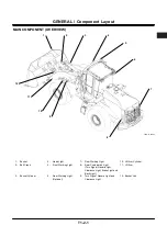
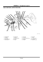
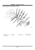
Page 38: ...GENERAL Component Specifications T1 3 14 Blank ...

Page 39: ...MEMO ...

Page 40: ...MEMO ...

Page 41: ...ering Circuit T2 3 26 Hydraulic Drive Fan Circuit T2 3 32 Group 4 Electrical System Outline T2 4 1 Main Circuit T2 4 2 Electric Power Circuit T2 4 3 Indicator Light Check Circuit T2 4 4 Accessory Circuit T2 4 5 Preheat Circuit T2 4 6 Starting Circuit T2 4 8 Charging Circuit T2 4 12 Serge Voltage Prevention Circuit T2 4 16 Engine Stop Circuit T2 4 18 Lamplight Circuit T2 4 19 Head Light Circuit T2 ...

Page 42: ...4GDT 2 2 Blank ...

Page 43: ... monitor unit display indications on the monitors and make various controls of the vehicle body by using the analog signals received by each controller as well as the digital signals detected on CAN ICF stores machine history receives the digital signals for various adjustments from Dr ZX transmits them to CAN and transmits the vehicle body information digital signal received by each controller to...

Page 44: ...sensors and switches necessary for indication of the monitor are trans mitted to the monitor unit and converted into the digital signals to be uploaded on CAN Each controller detects lacking information necessary for the control program from the CAN data digital signals Each controller makes various control program arith metic operations by using the detected data digital signals outputs the actua...

Page 45: ...for Ve hicle Body Solenoid Valves for Vehicle Body Sensor Switches for Cab and Monitor Relays for Cab MC ECM Monitor Unit ICF Engine Injectors Sensors and Switches Transmission Light Emitting Diode Solenoid Valves Sensors and Switches Switches for Traveling Dr ZX GPS ...

Page 46: ...ase Control Hydraulic Oil Temperature Sensor Other Controls Clutch Cut Position Switch Hydraulic Fan Cooling Control Lift Arm Angle Sensor OP Hydraulic Fan Cleaning Control Lift Arm Auto Leveler Upward Set Switch OP Transmission Failure Indicator Control Lift Arm Auto Leveler Downward Set Switch OP FNR Switch Enable Indicator Control Reverse Traveling Alarm Control Parking Brake Indrcator Control ...

Page 47: ...Speed Sensor Upshift Control Torque Converter Output Speed Sensor Clutch Cut Control Transmission Middle Shaft Sensor Speed Shift Holding Control Vehicle Speed Sensor Refer to the SYSTEM ECM System MC Refer to the SYSTEM ECM System group Engine Coolant Temperature Sensor ECM Torque Converter Oil Temeperature Sensor Monitor Unit NOTE ECM controls the engine speed and others based on the target engi...

Page 48: ...SYSTEM Control System T2 1 6 ENGINE CONTROL The engine controls consist of the followings Accelerator Pedal Control Auto Warming Up Control Engine Torque Control ...

Page 49: ...ctor Switch L N P Accelerator Pedal Sensor Accelerator Pedal Torque Converter Input Speed Sensor Transmission Engine Shift Switch MC ECM Monitor Unit Engine Coolant Temperature Sensor Hydraulic Oil Temperature Sensor Main Pump Delivery Pressure Sensor Torque Converter Output Speed Sensor ...

Page 50: ... accelerator pedal sen sor is 0 5 V to 4 5 V NOTE In case the accelerator pedal sensor be comes abnormal MC makes backup con trol and the engine speed is fixed at about 1100 min 1 NOTE In case MC becomes out of order or CAN fails ECM makes backup control and the engine speed is fixed at about 1100 min 1 NOTE In case MC becomes out of order with the accelerator remaining normal control of the engin...

Page 51: ...SYSTEM Control System T2 1 9 T4GC 02 01 003 Accelerator Pedal Sensor Accelerator Pedal Transmission Engine MC ECM Monitor Unit ...

Page 52: ...gnals and ECM decreases the engine slow idle speed to the idling speed NOTE At start of the engine if the hydraulic oil temperature is 1 C 34 F or above auto warming up control is not made NOTE In case the hydraulic oil temperature sen sor becomes abnormal auto warming up control is not made NOTE When the parking brake switch is turned OFF auto warming up control is released NOTE In case auto warm...

Page 53: ...SYSTEM Control System T2 1 11 T4GC 02 01 004 Transmission Engine MC ECM Monitor Unit Engine Coolant Temperature Sensor Hydraulic Oil Temperature Sensor ...

Page 54: ...ontrol of torque curves in response to the input torque curve se lection command signal NOTE In case the signal from the work mode se lector switch is not transmitted to MC backup control that the work mode is fixed to the normal mode is made NOTE In case the signal from the shift switch is not transmitted to MC backup control that Torque Curve 1 is selected is made NOTE Each mode switch of the wo...

Page 55: ... T4GD 02 01 007 NOTE The illustration shows the signal flow while mode L of work mode selector switch and speed 1 of the shift switch are selected Work Mode Selector Switch L N P Transmission Engine Shift Switch MC ECM Monitor Unit ...

Page 56: ...SYSTEM Control System T2 1 14 Blank ...

Page 57: ...Control Pump Control System Layout T4GD 02 01 008 Accelerator Pedal Sensor Accelerator Pedal Transmission Engine MC ECM Monitor Unit Main Pump Delivery Pressure Sensor Pump Torque Control Solenoid Valve Torque Converter Input Speed Sensor Torque Converter Output Speed Sensor Main Pump Regulator Hydraulic Oil Temperature Sensor ...

Page 58: ... engine speed 2 MC calculates the pump maximum displacement angle by receiving the target engine speed signal and hydraulic oil temperature and transmits the signal to the pump torque control solenoid valve 3 The pump torque control solenoid valve transmits pilot pressure according to the signal to the main pump regulator and controls the pump delivery flow rate NOTE In case the pump torque contro...

Page 59: ...Control System T2 1 17 T4GD 02 01 009 Accelerator Pedal Sensor Accelerator Pedal Transmission Engine MC ECM Monitor Unit Pump Torque Control Solenoid Valve Main Pump Regulator Hydraulic Oil Temperature Sensor ...

Page 60: ...s the pump delivery flow rate 4 If load applied to the engine becomes large and decreases the actual engine speed below the target speed the pump displacement angle is decreased and delivery flow rate is decreased Thus operation of the vehicle body is improved 5 MC calculates the actual engine speed by re ceiving the signal from the torque converter input speed sensor NOTE In case the accelerator ...

Page 61: ...l Switch Accelerator Pedal Transmission Engine MC ECM Monitor Unit Main Pump Delivery Pressure Switch Pump Torque Control Solenoid Valve Torque Converter Output Speed Sensor Torque Converter Input Speed Sensor Main Pump Regulator Hydraulic Oil Temperature Sensor ...

Page 62: ...n controls consist of the followings Neutral Control FNR Lever Priority Control Forward Reverse Selector Control While Travel ing Manual Speed Shift Control Automatic Speed Shift Control Downshift Control Upshift Control Clutch Cut Control Speed Shift Holding Control ...

Page 63: ... N R OFF ON ON OFF DOWN UP HOLD FNR Selector Switch Parking Brake Switch Upshift Downshift Switch Hold Switch Accelerator Pedal Accelerator Pedal Sensor Brake Pressure Sensor Brake Pedal Transmission Middle Shaft Sensor Forward Clutch Solenoid Valve Reverse Clutch Solenoid Valve MC ECM Monitor Unit Engine 1 2 3 Vehicle Speed Sensor Parking Brake Parking Brake Solenoid Valve Torque Converter Output...

Page 64: ... not transmit the signal to the clutch solenoid valve NOTE When the pilot pressure is transmitted the parking brake of the vehicle body is re leased NOTE In case short circuiting takes place inside the FNR lever the transmission is made neutral forcedly NOTE In case electric abnormality takes place involving the FNR switch traveling by the FNR lever is possible as an emergency measure NOTE The FNR...

Page 65: ...lected with the parking brake switch OFF Transmitting brake release signal FNR Lever FNR Switch F N R F N R OFF ON ON OFF FNR Selector Switch Parking Brake Switch Forward Clutch Solenoid Valve Reverse Clutch Solenoid Valve MC ECM Monitor Unit Engine Transmission Parking Brake Parking Brake Pressure Sensor Parking Brake Solenoid Valve ...

Page 66: ...is effective again by turning the FNR selector switch ON while both the FNR lever and the FNR switch are at the neutral position 3 Until the FNR lever is operated next from that time MC makes forward reverse control by the FNR switch input signal NOTE In case short circuiting takes place inside the FNR lever the transmission is made neutral forcedly and traveling becomes impossible which requires ...

Page 67: ...he signal flow in case forward of the FNR selector lever has been selected while traveling reverse of the FNR lever FNR Lever FNR Switch F N R F N R OFF ON FNR Selector Switch Forward Clutch Solenoid Valve Reverse Clutch Solenoid Valve MC ECM Monitor Unit Engine Transmission ...

Page 68: ...the signal to the reverse clutch solenoid valve and tarns the clutch into reverse 3 When the vehicle speed increases while the ac celerator pedal is depressed MC shifts up by sending the speed shift signal from speed 2 to speed 3 to each speed shift solenoid valve NOTE In case the FNR lever is operated when the vehicle speed is below the allowable speed of FNR clutch selection the FNR clutch is op...

Page 69: ...orward at speed 4 exceeding the allowable speed for shifting the FNR clutch Shift Switch FNR Lever FNR Switch F N R F N R OFF ON FNR Selector Switch Accelerator Pedal Accelerator Pedal Sensor Brake Pressure Sensor Brake Pedal Forward Clutch Solenoid Valve Reverse Clutch Solenoid Valve MC ECM Monitor Unit Engine 1 2 3 Speed Shift Solenoid Valve Transmission Vehicle Speed Sensor 4 ...

Page 70: ...NOTE When the shift switch is turned from speed 3 to speed 1 while traveling the vehicle automatically shifts down to speed 2 and then shifts down to speed 1 after the vehicle speed becomes the range of speed 1 NOTE In case a malfunction occurs in either so lenoid valve of speed 1 speed 3 or speed 4 the vehicle speed is fixed at speed 2 In case a malfunction occurs in either the forward clutch sol...

Page 71: ...n manual and the speed shift switch is set in speed 1 Travel Mode Switch Shift Switch FNR Lever FNR Switch M 1 4L 2 4N 1 4H F N R F N R OFF ON FNR Selector Switch Accelerator Pedal Accelerator Pedal Sensor Brake Pressure Sensor Brake Pedal Forward Clutch Solenoid Valve MC ECM Monitor Unit 1 2 3 Speed Shift Solenoid Valve Transmission Vehicle Speed Sensor Engine 4 ...

Page 72: ...d valve in response to the output value each time of the torque converter input speed sensor torque converter output speed sensor vehicle speed sensor and accelerater pedal sensor MC eventu ally makes speed shift control until the selected speed shift NOTE Each shift position specifies necessary ve hicle speed and accelerator pedal output value that allows shifting change to its posi tion The sett...

Page 73: ...while the brake pedal is depressed Travel Mode Switch Shift Switch FNR Lever FNR Switch M 1 4L 2 4N 1 4H F N R F N R OFF ON FNR Selector Switch Accelerator Pedal Accelerator Pedal Sensor Brake Pressure Sensor Brake Pedal Forward Clutch Solenoid Valve MC ECM Monitor Unit 1 2 3 Speed Shift Solenoid Valve Vehicle Speed Sensor Engine Transmission Torque Converter Output Speed Sensor Torque Converter I...

Page 74: ...he manual mode of the travel mode switch in case the vehicle speed is slow enough to shift down the speed shift is lowered and the shifted speed is kept 8 In case of the following the downshift switch con trol is canceled Operation of the FNR lever or the FNR switch Operation of the shift switch Operation of the travel mode switch Pushing the hold switch Only in auto mode of the travel mode switch...

Page 75: ...s set in auto 1 4L Travel Mode Switch Shift Switch FNR Lever FNR Switch M 1 4L 2 4N 1 4H F N R F N R OFF ON DOWN UP HOLD FNR Selector Switch Upshift Downshift Switch Hold Switch Accelerator Pedal Accelerator Pedal Sensor Brake Pressure Sensor Brake Pedal Transmission Middle Shaft Sensor Forward Clutch Solenoid Valve MC ECM Monitor Unit Engine 1 2 3 Speed Shift Solenoid Valve Transmission Vehicle S...

Page 76: ...e lected the raised speed shift is kept 6 In case of the following the upshift switch control is canceled Operation of the FNR lever or the FNR switch Operation of the shift switch Operation of the travel mode switch Pushing the hold switch only when the auto mode of the travel mode switch is selected NOTE Althrough the upshift switch is pushed while traveling at the speed shift slected by the shi...

Page 77: ...d the travel mode switch is set in auto 1 4L Travel Mode Switch Shift Switch FNR Lever FNR Switch M 1 4L 2 4N 1 4H F N R F N R OFF ON DOWN UP HOLD FNR Selector Switch Upshift Downshift Switch Hold Switch Accelerator Pedal Accelerator Pedal Sensor Brake Pressure Sensor Brake Pedal Forward Clutch Solenoid Valve MC ECM Monitor Unit Engine 1 2 3 Speed Shift Solenoid Valve Transmission Reverse Clutch S...

Page 78: ...t pressure of mode N and clutching is made again at output voltage below that of mode N In mode D clutch cut is made at output voltage of the brake pressure sensor beyond the set pressure of mode D and clutching is made again at output voltage below that of mode D 3 In case the brake pedal is depressed in mode S the signal from the brake pressure sensor is transmitted to MC 4 When the signal is hi...

Page 79: ... the signal flow in case the brake pedal has been depressed in mode S of the clutch cut position switch Clutch Cut Position Switch OFF S N D Brake Pressure Sensor Brake Pedal MC ECM Monitor Unit Engine Transmission Reverse Clutch Solenoid Valve Forward Clutch Solenoid Valve ...

Page 80: ...ions are made Turning the key switch OFF Pushing the hold switch again Downshift switch Upshift switch FNR lever FNR selector switch only when effective FNR switch only when effective Speed shift switch Travel mode switch Parking brake switch NOTE The shift switch has two switches and their combination of ON varies depending on each speed shift The controller judges which speed shift has been sele...

Page 81: ...1 4L 2 4N 1 4H F N R F N R OFF ON DOWN UP HOLD FNR Selector Switch Upshift Downshift Switch Hold Switch Accelerator Pedal Accelerator Pedal Sensor Brake Pressure Sensor Brake Pedal Forward Clutch Solenoid Valve MC ECM Monitor Unit 1 2 3 Engine Speed Shift Solenoid Valve Transmission 4 ON OFF Parking Brake Switch ...

Page 82: ...SYSTEM Control System T2 1 40 Blank ...

Page 83: ...S The other controls consist of the following Hydraulic Fan Cooling Control Hydraulic Fan Cleaning Control Transmission Failure Indicator Control FNR Switch Enable Indicator Control Reverse Traveling Alarm Control Parking Brake Indicator Control ...

Page 84: ...ves to the left 5 When the flow rate control valve spool moves to the left as a part of pressure oil to the fan motor flows to the tank port the fan motor speed is low ered accordingly 6 In case either oil temperature or coolant tem perature is above the set temperature the hy draulic fan speed is maximum when the engine speed is maximum 7 In case either oil temperature or coolant tem perature is ...

Page 85: ...c Oil Temperature Sensor MC ECM Monitor Unit Engine Coolant Tem perature Sensor Engine Trans mission Torque Converter Oil Temperature Sensor Fan Pump Hydraulic Oil Tank Fresh Air Temperature Sensor Air Conditioner Control Panel Flow Rate Control Valve Flow Rate Control Solenoid Valve Hydraulic Oil Temperature Sensor Engine Coolant Temperature Sensor Engine Trans mission Torque Converter Oil Temper...

Page 86: ...re changed during reverse rotation the engine speed is immediately fixed to idle speed 5 Hydraulic fan cleaning control is not released only by turning the fan reverse rotation switch OFF This control is released by the procedure of turn ing the fan reverse rotation switch OFF turning the key switch OFF turning the key switch ON 6 In case the engine speed is fixed to idle speed this control is rel...

Page 87: ...ion Reverse Rotation Spool Reverse Rotation Control Solenoid Valve Hydraulic Oil Tank Engine Trans mission Reverse Rotation Spool Reverse Rotation Control Solenoid Valve OFF ON Fan Reverse Rotation Switch MC ECM Monitor Unit F N R F N R ON OFF FNR Lever FNR Switch Parking Brake Switch Fan Motor Hydraulic Oil Tank Parking Brake Solenoid Valve Parking Brake Pressure Sensor ...

Page 88: ...mes out of order MC transmits the signal to the monitor unit and lights the transmission failure indicator Torque converter input speed sensor Torque converter output speed sensor Vehicle speed sensor Transmission middle shaft sensor FNR lever FNR switch T4GD 02 01 006 Engine Transmission MC ECM Monitor Unit F N R FNR Lever FNR Switch Monitor Transmission Failure Indicator F N R Torque Converter I...

Page 89: ...ecomes out of order input to the FNR switch becomes ineffective and the FNR switch enable indicator is kept OFF NOTE In case the FNR lever is operated while traveling by using the FNR switch input to the FNR switch becomes ineffective and the vehicle body moves by operating the FNR lever Refer to the FNR Lever Priority Control NOTE The FNR switch does not transmit the neu tral signal In case of no...

Page 90: ...ration 1 When reverse of the FNR lever or the FNR switch is selected MC grounds the terminal from the reverse light relay 2 The reverse light relay is excited and current flows to the reverse light and the reverse buzzer T4GD 02 01 004 MC ECM Monitor Unit F N R FNR Lever or FNR Switch Reverse Buzzer Right Reverse Light Left Reverse Light Reverse Light Relay From 11 of Fuse Box A From 8 of Fuse Box...

Page 91: ...r NOTE The parking brake of the vehicle body is released if pilot pressure is routed NOTE As for operation circuit of the parking brake refer to the SYSTEM Electric System group IMPORTANT Be careful that in case the parking brake pressure sensor is abnormal traveling is possible although the parking brake switch is ON and the parking brake is applied as the park ing brake indicator is fixed to OFF...

Page 92: ...SYSTEM Control System T2 1 50 Blank ...

Page 93: ...D CIRCUIT The electric and hydraulic combined circuit has the following controls Ride Control Optional Bucket Auto Leveler Control Lift Arm Float Control Lift Arm Kick Out Control Lift Arm Auto Leveler Upward Control Optional Lift Arm Auto Leveler Downward Control Optional ...

Page 94: ...ensor and transmits current to the ride control solenoid valve 3 When the ride control solenoid valve is operated and the spool moves a damper circuit is organ ized between the rod side and the bottom side of the lift arm cylinder When the vehicle body travels on rough roads the fluctuation of the bottom pressure of the lift arm cylinder is absorbed by the ride control accumulator and the shock of...

Page 95: ...itor Unit OFF ON Ride Control Switch Ride Control Indicator Engine Trans mission Vehicle Speed Sensor Lift Arm Cylinder To Control Valve Ride Control Accumulator Ride Control Valve Relief Valve Ride Control Solenoid Valve Spool Pilot Pump Hydraulic Oil Tank ...

Page 96: ...e bucket control lever is retained by the electromagnet on the bucket tilting side and pressure oil from the pilot valve moves the bucket spool in the control valve 3 Pressure oil from the main pump flows to the bottom side of the bucket cylinder through the bucket spool in the control valve and extends the bucket cylinder When the bucket cylinder is ex tended the bar also passes by the bucket pro...

Page 97: ... 55 T4GD 02 01 001 From Fuse 6 of Fuse Box B Bucket Cylinder Bucket Control Valve Electromagnet on Bucket Tilting Side Bucket Pilot Valve Bucket Proximity Switch Bar Main Pump Hydraulic Oil Tank Pilot Pump Lift Arm Leveler Relay ...

Page 98: ... the engine is running the electro magnet on the lift arm lowering side is al ways excited by current from fuse 6 of fuse box B 2 Pressure oil from the main pump is blocked by the lift arm spool and the ports on the rod side and the bottom side of the lift arm cylinder are con nected to the tank port through the lift arm spool As the both ports of the lift arm cylinder have the same pressure as th...

Page 99: ... 1 57 T4GB 02 01 014 Lift Arm Rod Side Port Lift Arm Cylinder Control Valve Bottom Side Port From Fuse 6 of Fuse Box B Electromagnet on Lift Arm Lowering Side Lift Arm Pilot Valve Main Pump Hydraulic Oil Tank Pilot Pump Bucket ...

Page 100: ... the bucket control lever is retained by the electromagnet on the lift arm raise side and pressure oil from the pilot valve moves the lift arm spool in the control valve to the raise side 3 Pressure oil from the main pump flows to the bottom side of the lift cylinder through the lift arm spool in the control valve and extends the lift arm cylinder When the lift arm cylinder is extended the plate a...

Page 101: ...1 002 Lift Arm Proximity Switch Control Valve Lift Arm Cylinder Plate Bottom Side Port Rod Side Port Lift Arm Pilot Valve From Fuse 6 of Fuse Box B Electromagnet on Lift Arm Raise Side Lift Arm Main Pump Hydraulic Oil Tank Pilot Pump Bucket ...

Page 102: ...rm control lever is retained by the elec tromagnet on the lift arm raise side and pressure oil from the pilot valve is supplied to the control valve 3 Pressure oil from the main pump flows to the bottom side port of the lift cylinder through the lift arm spool in the control valve and raises the lift arm 4 When the lift arm angle sensor moves to the lift arm auto leveler upward stop position termi...

Page 103: ...l Valve Lift Arm Cylinder Link Bottom Side Port Rod Side Port SET ON Lift Arm Auto Leveler Upward Set Switch Lift Arm Pilot Valve From Fuse 6 of Fuse Box B Electromagnet on Lift Arm Raise Side Lift Arm OFF D 10 B 11 B 20 A 25 MC Main Pump Hydraulic Oil Tank Pilot Pump Bucket ...

Page 104: ...lowering position the lift arm operation lever is retained by the electromagnet on the lift arm lowering side and pressure oil from the pilot valve is supplied to the control valve 3 Pressure oil from the main pump flows to the rod side port of the lift cylinder through the lift arm spool in the control valve and lowers the lift arm 4 When the lift arm angle sensor moves to the lift arm auto level...

Page 105: ...ensor Control Valve Lift Arm Cylinder Link Bottom Side Port Rod Side Port SET ON Lift Arm Auto Leveler Downward Set Switch Lift Arm Pilot Valve From Fuse 6 of Fuse Box B Electromagnet on Lift Arm Lowering Side Lift Arm OFF D 10 B 19 B 3 B 22 MC Bucket Pilot Pump ...

Page 106: ...SYSTEM Control System T2 1 64 Blank ...

Page 107: ...pressure pump is driven by the engine and produces high pressure fuel The common rail distributes high pressure fuel produced by the high pressure pump to the injector in each engine cylinder The injector injects high pressure fuel from the common rail T4GD 02 02 001 Engine Speed Sensor Crankshaft Engine Position Sensor Camshaft Ambient Pressure Sensor Coolant Temperature Sensor Intake Manifold Pr...

Page 108: ... oil pressure switch and common rail pressure sensor and detects the engine operating condition 2 When detecting the signal from MC ECM processes and controls the fuel injection of injector while detecting the engine operating condition 3 The solenoid valve is attached to the injector The solenoid valve controls operation of start and stop for injection according to the signal form ECM NOTE MC sen...

Page 109: ...ressure Sensor Common Rail Injector High Pressure Pump Engine Speed Sensor Crankshaft Engine Position Sensor Camshaft Ambient Pressure Sensor Coolant Temperature Sensor Intake Manifold Pressure Sensor Intake Manifold Temperature Sensor Engine Oil Pressure Switch ...

Page 110: ...ntake manifold temperature sensor sends the signals according to temperature in the intake manifold to ECM 2 ECM controls the exciting time of intake air heater relay according to the signal Therefore the time for continuity of current for intake air heater is controlled Refer to the Electrical System group T4GD 02 02 003 Intake Manifold Temperature Sensor ECM From Battery Relay Intake Air Heater ...

Page 111: ... Control Engine Warning Indicator Control Engine Warning Indicator and Stop Indicator Control T4GD 02 02 004 Diode B 48 43 44 Diode H 49 Engine Oil Pressure Relay 1 7 1 8 2 22 2 21 Engine Oil Low Pressure Indicator Stop Indicator Service Indicator Engine Warning Indicator Overheat Relay ECM Diode G Monitor Unit Overheat Indicator From Fuse 9 of Fuse Box B ...

Page 112: ... the monitor unit is grounded the monitor unit lights the overheat indicator 3 When the engine coolant temperature returns to the normal value ECM demagnetizes the overheat relay Therefore terminal 1 7 of the monitor unit is disconnected from the ground 4 When terminal 1 7 of the monitor unit is disconnected from the ground the monitor unit turns off the overheat indicator NOTE The monitor unit li...

Page 113: ... is grounded the monitor unit lights the engine oil pressure indicator 3 When the engine lubricant oil pressure returns to the normal range ECM demagnetizes the engine oil pressure relay Therefore terminal 1 8 of the monitor unit is disconnected form the engine 4 When terminal 1 8 of the monitor unit is disconnected form the engine the monitor unit turns off the engine oil low pressure indicator N...

Page 114: ...is grounded the monitor unit lights the engine warning indicator 3 When the engine returns to normal conditions ECM deactivates the ground connection to terminal 44 Therefore terminal 2 21 of the monitor unit is disconnected form the engine 4 When terminal 2 21 of the monitor unit is disconnected form the engine the monitor unit turns off the engine warning indicator NOTE The monitor unit lights t...

Page 115: ...or unit are grounded the monitor unit lights the engine warning indicator and stop indicator 3 When the engine returns to normal conditions ECM deactivates the ground connection to terminal 43 Therefore terminals 2 21 and 2 22 of the monitor unit are disconnected form the engine 4 When terminals 2 21 and 2 22 of the monitor unit are disconnected form the engine the monitor unit turns off the engin...

Page 116: ...SYSTEM ECM System T2 2 10 Blank ...

Page 117: ...ol circuit brake circuit and ride control circuit optional composed of the pilot pump charging block and valves to control each circuit Steering Circuit Steering circuit consists of the normal steering circuit steering shockless circuit emergency steering circuit optional steering stop circuit composed of the pump priority valve steering valve cylinders and other valves Hydraulic Drive Fan Circuit...

Page 118: ...gh the priority valve Pressure oil to the steering valve flows to the steering cylinders in response to operation of the spool in the steering valve and the return oil flows back to the hydraulic oil tank through the steering valve Pressure oil to the control valve flows to the cylinders in response to operation of the spool in the control valve and the return oil flows back to the hydraulic oil t...

Page 119: ... Hydraulic System T2 3 3 T4GD 02 03 006 Steering Cylinder Steering Valve Bucket Cylinder Lift Arm Cylinder Control Valve Bucket Spool Lift Arm Spool Priority Valve Main Pump Suction Filter Hydraulic Oil Tank ...

Page 120: ...the notch to lead pressure oil from the main pump to the steering valve moves until the delivery port on the steering valve side in the priority valve is closed When pressure balance is obtained and the spool stops moving When the steering valve spool moves the tank port connected to port LS2 is closed At this time as port LS2 is connected to the main circuit through the steering valve spool press...

Page 121: ...operation while the engine is running Steering Cylinder Bucket Cylinder Lift Arm Cylinder Control Valve Steering Valve Priority Valve LS 1 Main Pump Hydraulic Oil Tank Hydraulic Oil Tank Hydraulic Oil Tank Spool Bucket Lift Arm At Stop of Engine Orifice 1 Spool LS 2 Orifice 3 Orifice 2 Spring ...

Page 122: ... oil is supplied to the steering valve Therefore the steering valve is not provided with a neutral circuit Refer to Priority Valve Circuit in this section Single Operation Circuit Pressure oil from the main pump flows to the control valve and flows to the lift arm and bucket spools When the steering valve spool moves the priority valve spool moves leftward and pressure oil from the main pump flows...

Page 123: ...ustration shows oil flow without operation while the engine is running Steering Cylinder Bucket Cylinder Lift Arm Cylinder Control Valve Steering Valve Priority Valve Main Pump Hydraulic Oil Tank Hydraulic Oil Tank Hydraulic Oil Tank Spool Bucket Lift Arm Spool ...

Page 124: ...pool moves rightward Therefore pressure oil from the main pump flows to the lift arm cylinder through the check valve and the lift arm spool in the control valve and raises the lift arm Pressure oil from the main pump also flows to the buket cylinder through the check valve orifice and bucket spool in the control valve and dumps the bucket Although lift arm raising operation is more heavy loaded t...

Page 125: ...lve Orifice Steering Cylinder Lift Arm Cylinder Control Valve Steering Valve Priority Valve Spool Main Pump Bucket Cylinder LS 2 LS 1 Hydraulic Oil Tank Hydraulic Oil Tank Bucket Lift Arm Spring From Pilot Valve Lift Arm Raise From Pilot Valve Bucket Dump ...

Page 126: ...ard drastically Flow rate and direction of the main pump are controlled by the leftward movement of the priority valve spool The oil flow rate corresponding to the movement flows to the steering valve and the remainder flow rate flows to the control valve NOTE If the steering wheel is turned quickly and largely for reasons of avoiding danger or something the priority valve spool largely moves left...

Page 127: ...t Arm Cylinder Control Valve Steering Valve Check Valve Priority Valve Spring LS 2 LS 1 Spool Main Pump Hydraulic Oil Tank Hydraulic Oil Tank Bucket Lift Arm Spool Hydraulic Oil Tank From Steering Pilot Valve Right Steering From Pilot Valve Lift Arm Raise Orifice 2 Orifice 3 Orifice 1 ...

Page 128: ...SYSTEM Hydraulic System T2 3 12 Blank ...

Page 129: ...Control Circuit Optional T4GC 02 02 001 Pilot Shut Off Valve Lift Arm Pilot Valve Bucket Pilot Valve Option Pilot Valve Control Valve Charging Block Brake Valve Service Brake Parking Brake Main Pump Regulator Ride Control Solenoid Valve Pilot Filter Pilot Pump Suction Filter Hydraulic Oil Tank Brake Circuit Pump Control Circuit Ride Control Circuit Optional Front Attachment Circuit Spool Ride Cont...

Page 130: ... is closed In this case only pilot pressure is applied to port B of the priority valve As both pilot pressure and the spring force are applied to port A the priority valve moves rightward and controls pressure oil to flow further Pressure oil from the pilot pump flows to the service brake circuit through the check valve and accumulates the service brake accumulators To be continued to T2 3 16 NOTE...

Page 131: ...w when the relief valve and the priority valve are closed in response to pressure decrease in the service brake circuit Brake Pedal Front Brake Rear Brake Relief Valve Service Brake Accumulator Check Valves Priority Valve Charging Block Pilot Pump Brake Valve Service Brake A Spring B ...

Page 132: ...aged Pressure oil from port PS1 passes the steering pilot valve and is supplied for actuation of the steering valve spool Refer to Steering Circuit Pressure oil from port X changes its flow in response to the stroke of the pump torque control solenoid valve which is controlled by the signal from MC and is used to control the main pump regulator Refer to Pump Control Circuit Pressure oil from port ...

Page 133: ...s open and the pilot shut off valve is open Pilot Shut Off Valve Lift Arm Pilot Valve Bucket Pilot Valve Auxiliary Pilot Valve Optional To Service Brake Circuit Priority Valve Pilot Pump Charging Block Service Brake Accumulator Relief Valve A Parking Brake Solenoid Valve Pilot Relief Valve PS 1 X Parking Brake Pressure Sensor BR3 PP Pump Torque Control Solenoid Valve Spring B Hydraulic Oil Tank PS...

Page 134: ...it when pressure in the service brake accumulators is lowered Refer to Charging Block Circuit The pilot shut off valve is a manually operated type and is installed in order to prevent accidents due to wrong operation by stopping suppy of pressure oil to the pilot valve when it is closed By controlling each pilot valve pressure oil from the pilot pump shifts the control valve spools At both ends of...

Page 135: ...lve when the service brake accumulators are pressurized the priority valve is open and the pilot shut off valve is open Pilot Shut Off Valve Lift Arm Pilot Valve Bucket Pilot Valve Auxiliary Pilot Valve Optional Control Valve To Service Brake Circuit Priority Valve Slow Return Valve 1 2 3 4 5 6 7 8 8 6 2 7 5 1 3 Pilot Pump Main Pump Charging Block Auxiliary 2 Auxiliary 1 Bucket Lift Arm Service Br...

Page 136: ...l by Flow Control Pressure Pi1 Pi2 Pressures upward and downward the orifice Pi1 and Pi2 of the pump flow control valve installed at the farthest downstream of the control valve neutral circuit are supplied to the main pump regulator in order to adjust the pump flow Pump Flow Control by Pump Torque Control Solenoid Valve The signal from MC actuates the pump torque control solenoid valve and contro...

Page 137: ...2 3 21 T4GD 02 03 004 Charging Block Pump Torque Control Solenoid Valve Pi2 Pi1 Servo Piston Pilot Pump Main Pump Main Pump Regulator Hydraulic Oil Tank Command Signal from MC PS2 Control Valve Orifice Pump Flow Control Valve X ...

Page 138: ...o that the priority valve is not completely closed Although the priority valve is closed completely a certain amount of pressure oil is being supplied to the circuits downstream NOTE Although the engine is stopped the service brake circuit pressure is retained for a while due to the functions of the service brake accumulators and the check valve Parking Brake Circuit Pressure oil from the pilot pu...

Page 139: ...so oil flow when the parking brake is applied with the unexcitement of the parking brake solenoid valve Brake Pedal Front Brake Rear Brake Parking Brake Applied Released Relief Valve Service Brake Accumulator Check Valve Priority Valve Charging Block Pilot Pump Brake Valve Service Brake No Signal for Parking Brake Release Parking Brake Solenoid Valve Parking Brake Pressure Sensor Spring Pilot Accu...

Page 140: ...ride control switch is turned ON the ride control solenoid valve is excited and the spool moves downward As the bottom end of the lift arm cylinder is connected to the ride control accumulator the rod side of the lift arm cylinder is connected to the hydraulic oil tank In this way the force to raise the front attachment is relieved to the hydraulic oil tank and the force to lower the front attachm...

Page 141: ...stration shows oil flow when the ride control solenoid valve is excited Lift Arm Cylinder Ride Control Accumulator To Control Valve Ride Control Valve Ride Control Solenoid Valve Spool Charge Cut Spool Pilot Pump Ride Control Operation Signal Hydraulic Oil Tank ...

Page 142: ...lve spool moves quickly and largely When the steering wheel is slowly turned as a small amount of pilot pressure oil is supplied gradually to the end of the steering valve spool through the steering pilot valve the steering valve spool moves slowly and slightly In proportion to the movement of the steering valve spool pressure in pilot line LS2 rises Therefore the priority valve spool is pushed le...

Page 143: ...t Steering Cylinder Steering Valve Orifice Steering Pilot Valve Gerotor Pump Delivery Pressure Switch Emergency Steering Pump Unit To Control Valve Priority Valve Spring LS 2 LS 1 Spool Steering Wheel Pilot Pump Main Pump Steering Accumulator Spool Orifice Hydraulic Oil Tank Hydraulic Oil Tank Emergency Steering Pump Delivery Pressure Switch ...

Page 144: ...ivery is stopped or drastically decreased caused by failure of the engine or the main pump the pressure sensing signal of the pump delivery pressure switch is transmitted into the monitor controller Then the monitor controller starts the motor of the emergency steering pump unit Pressure oil is supplied from the emergency steering pump for 1 minute Therefore steering operation is possible When 1 m...

Page 145: ...o the right Steering Cylinder Steering Valve Orifice Steering Pilot Valve Gerotor Pump Delivery Pressure Switch Emergency Steering Pump Unit To Control Valve Priority Valve Spring LS 2 LS 1 Spool Steering Wheel Pilot Pump Main Pump Steering Accumulator Spool Orifice Emergency Steering Pump Delivery Pressure Sensor Hydraulic Oil Tank ...

Page 146: ... the steering valve from the steering pilot valve is blocked Consequently as the steering valve spool is in neutral supply of pressure oil from the main pump to the steering cylinders is stopped T4GB 02 02 004 NOTE The illustration shows the oil flow when the stop valve is closed during the right steering Steering Cylinder Steering Valve Stop Valve Stop Valve Contact External Force Steering Pilot ...

Page 147: ...SYSTEM Hydraulic System T2 3 31 Blank ...

Page 148: ...ntrol valve end in response to the stroke when the flow adjusting solenoid valve is excited When the flow rate control valve is operated pressure oil from the fan pump to the fan motor is restricted and speed of the fan motor is controlled When the fan reverse rotation switch is turned ON current flows from MC to the reverse rotation control solenoid valve When the reverse rotation control solenoi...

Page 149: ...s the pressure oil flow without any control Fan Motor Reverse Rotation Spool Reverse Rotation Control Solenoid Valve Flow Control Valve Flow Adjusting Solenoid Valve Fan Pump Reverse Rotation Signal from MC Flow Adjustment Signal from MC Hydraulic Oil Tank Hydraulic Oil Tank ...

Page 150: ...SYSTEM Hydraulic System T2 3 34 Blank ...

Page 151: ...it Circuit for traveling composed of head lights turn signals brake lights and horn Control Circuit Refer to the SYSTEM Control System group Control circuit for engine pumps transmission and valves composed of actuators as solenoid valves MC main controller ECM engine control module ICF information controller monitor unit switches sensors and pressure switches In this group functions and compositi...

Page 152: ...nd indicators Accessory Circuit for working at ACC of the key switch Preheat Circuit for assisting engine start in cold weather Starting Circuit for starting engine Charging Circuit for supplying electricity to the battery and replenishing electricity Surge Voltage Prevention Circuit for preventing occurrence of surge voltage at stop of the engine Engine Stop Circuit for stopping the engine by ECM...

Page 153: ...mount of current is supplied to the circuit Disconnect the battery ground terminal in case of a long downtime T4GD 02 04 007 Head Light Switch Key Switch Fuse Box B Fusible Link Battery Relay Battery 7 8 9 14 15 18 19 20 Fuse Box B Fuse 7 Key Switch Head Light Switch Fuse 8 Flasher Relay Interior Light Radio Fuse 9 Load Dump Relay Fuse 14 GPS ICF MC Optional Control Unit Optional Fuse 15 ECM Relay...

Page 154: ...witch Current from terminal M of the key switch flows from fuse 8 of fuse box A to terminal 1 2 of the monitor unit The monitor unit checks the bulbs breakage of warning lamp and indicator by lighting them and also starts the liquid crystal display T4GD 02 04 011 Key Switch Monitor Unit Fusible Link Battery Relay Battery 1 2 Fuse Box A 8 From Fuse 7 of Fuse Box B To Fuse 7 of Fuse Box B ...

Page 155: ...CC position terminal B is connected to terminal ACC inside the key switch Current from terminal ACC of the key switch flows from fuse 10 of fuse box B to terminal 3 of the radio and makes the radio operable T4GB 02 03 003 Key Switch Fuse Box B Radio Fusible Link Battery Relay Battery 7 10 ...

Page 156: ...7 of fuse box A flows to terminal 39 of ECM ECM controls the exciting time of the intake air heater relay While the intake air heater relay is excited power is supplied to the intake air heater from the intake air heater relay and preheats it While preheating is made as terminal 50 of ECM is grounded current flows from terminal 1 24 of the monitor unit to terminal 50 of ECM Therefore the monitor u...

Page 157: ...s made with the intake air heater relay excited and the power supplied to the intake air heater Key Switch Fuse Box A Fusible Link Battery Relay Battery Intake Air Heater Relay Intake Air Heater Fuse 120A Preheat Indicator Monitor Unit 1 24 39 40 42 50 ECM To Fuse 7 of Fuse Box B From Fuse 7 of Fuse Box B 8 7 ...

Page 158: ...elay When the key switch is turned to the START position continuity between terminals B and ST of the key switch is made Current flows to the base of transistor Q2 through resistance R4 inside the starter relay Transistor Q2 is turned ON and current flows to coil L of the relay Consequently terminals 30 and 50 of the starter are connected and the starter is operated When the engine is started the ...

Page 159: ...hen the FNR lever and the FNR switch are in the neutral position Key Switch Fuse Box A Neutral Relay Fusible Link Battery Relay Battery Starter Relay Starter Motor Alternator Fuse 120A To Key ON Signal Monitor Unit ECM ICF 8 To Fuse 7 of Fuse Box B From Fuse 7 of Fuse Box B MC B 16 A 27 30 50 G ...

Page 160: ...relay By exciting the battery relay the battery power flows to terminals B of the starter motor and the starter relay At this time when either of the FNR lever or the FNR switch is in the forward or reverse position terminal A 27 of MC is connected to the ground and the neutral relay is excited By exciting the neutral relay the circuit between the neutral relay and terminal S of the starter relay ...

Page 161: ... current flow when either of the FNR lever or the FNR switch is in the forward or reverse position Key Switch Fuse Box A Neutral Relay Fusible Link Battery Relay Battery Starter Relay Starter Motor Fuse 120A 8 To Fuse 7 of Fuse Box B From Fuse 7 of Fuse Box B MC B 16 A 27 30 50 G ...

Page 162: ...hrough fuse 8 of fuse box A When the engine rotates the alternator begins generating electricity Current from terminal B of the alternator flows to the battery through the battery relay and charges the battery Current from terminal L of the alternator flows to terminal 2 2 of the monitor unit as a signal that the alternator begins generating and the monitor unit turns off the alternator indicator ...

Page 163: ...13 T4GD 02 04 015 Key Switch Fuse Box A Fusible Link Battery Relay Battery Starter Relay Starter Motor Alternator Fuse 120A Monitor Unit 2 2 A 3 C 8 GPS ICF Alternator Lamp 8 To Fuse 7 of Fuse Box B From Fuse 7 of Fuse Box B G 30 50 ...

Page 164: ...ing through field coil FC increases Therefore generating voltage increases further and the batteries start charging Operation of Regulator The regulator is an IC chip which maintains generating voltage at a constant level When generating voltage exceeds the set voltage the regulator decreases current through field coil FC This decreases generating voltage of stator coil SC When generating voltage ...

Page 165: ...SYSTEM Electrical System T2 4 15 T4GD 02 04 019 Battery Relay Battery SC FC L L B E D Alternator B Regulator F R ...

Page 166: ...e controller possibly cause In order to prevent the occurrence of surge voltage the surge voltage prevention circuit is provided When the alternator is generating electricity generating current from terminal L of the alternator flows to terminal 2 2 of the monitor unit The monitor unit connects terminal 2 10 to the ground Current flows through the load dump relay exciting circuit and the load dump...

Page 167: ...YSTEM Electrical System T2 4 17 T4GD 02 04 016 Key Switch Fusible Link Battery Relay Battery Starter Relay Starter Motor Alternator Fuse 120A Monitor Unit 2 10 2 2 Load Dump Relay 9 30 50 7 Fuse Box B G ...

Page 168: ... 30 seconds after the key switch is OFF by the timer function Thus current flows to terminals 3 and 4 of ECM and ECM is kept ON After 30 seconds the timer stops and ECM is turned OFF T4GD 02 04 018 NOTE The illustration shows the current flow when the timer is working with the key switch OFF Key Switch Fuse Box A Fusible Link Battery Relay Battery Fuse 120A Fuel Injection Solenoid Valve ECM 39 8 7...

Page 169: ...ls Brake Light Circuit for turning on and off brake lights Hazard Light Circuit for turning on and off hazard lights Horn Circuit for sounding horn Reverse Light Buzzer Circuit for turning on and off reverse lights and reverse buzzer Parking Brake Circuit for applying and releasing parking brake Emergency Steering Check Circuit Optional for confirming operation of emergency steering pump unit ...

Page 170: ...rom terminal S of the head light switch enters terminal 1 21 of the monitor unit and the illumination light of the monitor unit lights Another of power from terminal S of the head light switch is divided into to fuse 16 and fuse 17 of fuse box B Power from fuse 16 of fuse box B lights front right and rear left clearance lights Power from terminal 42 of fuse box B lights the license light and the f...

Page 171: ...ight Switch Fuse Box A Fusible Link Battery Relay Battery Front Left Clearance Light Monitor Unit Illumination Light Rear Left Clearance Light Front Right Clearance Light Rear Right Clearance Light License Light Key Switch 1 21 Fuse Box B 7 16 17 Fuse 120A ...

Page 172: ...en the head light switch is positioned at Head Light the power from terminal S lights each of the clearance lights Refer to Clearance Light Lighting Circuit and the power from terminal H flows to the dimmer switch At this time if the dimmer switch is turned to Lo Low Beam the power enters the right head light relay and the left head light relay The battery power enters the head lights and lights t...

Page 173: ... A Fusible Link Battery Relay Battery Monitor Unit High Beam Indicator Right High Beam Light Key Switch 1 22 Dimmer Switch Right Head Light Relay Left Head Light Relay Right Head Light High Beam Relay Fuse Box B Left High Beam Light Left Head Light Lo Hi 7 12 15 8 5 Fuse 120A ...

Page 174: ...ar left turn signal lights and terminal 1 19 of the monitor unit through the left turn signal relay Consequently the front and rear left turn signal lights and the left turn signal indicators blink T4GD 02 04 005 Front Right Turn Signal Light Front Left Turn Signal Light Left Turn Signal Fusible Link Battery Relay Battery Rear Left Turn Signal Light Monitor Unit Right Turn Signal Key Switch 1 19 T...

Page 175: ... through fuse 12 of fuse box A When the brake pedal is depressed the brake light switch is grounded Therefore the brake light relay is excited and the battery power enters the brake lights and lights them T4GD 02 04 003 Fuse Box A Fusible Link Battery Relay Battery Key Switch Brake Light Relay Brake Pedal Brake Light Switch Right Brake Light Left Brake Light To Fuse 7 of Fuse Box B From Fuse 7 of ...

Page 176: ...ignal lights and terminals 1 19 and 1 20 of the monitor unit through the left and right turn signal relays Consequently all of the front rear left and right turn signal lights and the left and right turn signal indicators blink T4GD 02 04 006 Fusible Link Battery Relay Battery Rear Left Turn Signal Light Monitor Unit Right Turn Signal Key Switch 1 19 Turn Signal Switch Flasher Relay Rear Right Tur...

Page 177: ... The battery power is routed to the horn relay through fuse 14 of fuse box A When the horn switch is pushed it is grounded Therefore the horn relay is excited The battery power enters the horn and the horn sounds T4GD 02 04 008 Fusible Link Battery Relay Battery Key Switch Horn Relay Horn Switch Horn To Fuse 7 of Fuse Box B From Fuse 7 of Fuse Box B Fuse Box A 8 14 Fuse 120A ...

Page 178: ...fuse 8 of fuse box A The battery power enters the reverse light relay through fuse 11 of fuse box A When the FNR lever is turned to reverse terminal R is grounded The power flows to the FNR lever from terminal B 6 of MC and terminal A 26 of MC is grounded Therefore the reverse light relay is excited and the battery power flows to the reverse light and the reverse buzzer ...

Page 179: ... T4GD 02 04 009 Fusible Link Battery Relay Battery Key Switch Reverse Light Relay FNR Lever Reverse Buzzer MC A 26 Right Reverse Light B 6 Left Reverse Light Fuse Box A 8 11 To Fuse 7 of Fuse Box B From Fuse 7 of Fuse Box B Fuse 120A ...

Page 180: ...y 2 is excited as current from terminal L of the alternator enters terminal 2 2 of the monitor unit and releases grounded terminal 2 18 of the monitor unit Consequently a circuit in which electricity flows from terminal C of parking brake relay 2 to terminal A of parking brake relay 2 and the parking brake solenoid valve self exciting circuit is formed Therefore the parking brake solenoid valve is...

Page 181: ...rned OFF with the engine running Fuse 120A Battery Relay Battery Key Switch Parking Brake Relay 1 Parking Brake Relay 2 Parking Brake Switch ON OFF A B E F GH A B CD E A B CD E When forming a self exciting circuit NEUTRAL 2 18 Monitor Unit 2 2 From Terminal L of Alternator 2 18 Monitor Unit 2 2 From Terminal L of Alternator From Fuse 2 of Fuse Box B Fuse Box A 8 2 Fusible Link 7 ...

Page 182: ...he key switch to the ST position the alternator starts generating electricity When part of the electricity generating signal from terminal L of the alternator enters the monitor unit and increases to the specified voltage terminal 2 11 of the monitor unit is grounded and the emergency steering relay is excited The power enters terminal C of the emergency steering pump unit through the emergency st...

Page 183: ... Box A Fuse 120A Battery Relay Battery Key Switch Emergency Steering Relay Emergency Steering Check Switch 2 14 Monitor Unit Emergency Steering Pump Unit Fuse Box B 8 6 7 2 2 Alternator Emergency Steering Pump Delivery Pressure Sensor Fusible Link 1 14 ...

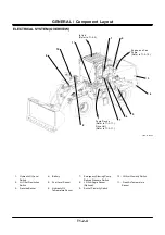
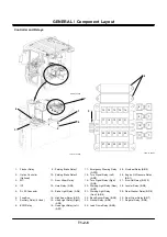
Page 184: ...SYSTEM Electric System T2 4 34 Blank ...

Page 185: ...MEMO ...

Page 186: ...MEMO ...

Page 187: ...Flow Rate Control Valve T3 3 6 Reverse Rotation Control Valve T3 3 8 Fun Pump T3 3 10 Group 4 Steering Pilot Valve Outline T3 4 1 Construction T3 4 2 Operation T3 4 3 Group 5 Steering Valve Outline T3 5 1 Operation T3 5 4 Steering Overload Relief Valve T3 5 8 Group 6 Pilot Valve Outline Standard Lever Type Pilot Valve for Front Attachment T3 6 1 Operation T3 6 2 Electromagnetic Detent T3 6 6 Outli...

Page 188: ...Plug T3 8 11 Group 9 Drive Unit Outline T3 9 1 Torque Converter T3 9 2 Transmission T3 9 4 Transmisson Regulator Valve T3 9 26 Transmission Control Valve T3 9 28 Manual Spool Emergency Travel Spool T3 9 36 Proportional Solenoid Valve T3 9 38 Parking Brake T3 9 40 Group 10 Axle Outline T3 10 1 Differential T3 10 2 Torque Proportioning Differential TPD T3 10 6 Limited Slip Differential LSD Optional ...

Page 189: ...itted to shaft 3 through the transmission input shaft and actuates main pump 1 and pilot pump 2 Main pump 1 is a swash plate type variable displacement axial plunger pump Pilot pump 2 is a gear pump Pump delivery pressure sensor 4 is provided in order to control the main pump T4GB 03 01 001 1 Main Pump 3 Shaft 5 Steering Main Relief Valve 2 Pilot Pump 4 Pump Delivery Pressure Sensor 6 Priority Val...

Page 190: ...tate together When cylinder block 1 rotates plungers 2 reciprocates inside the cylinder block due to the tilting of swash plate 4 and delivers the hydraulic oil The main pump delivery flow is controlled by changing the displacement angle of swash plate 4 with servo piston 1 3 and servo piston 2 6 which increase or decrease the stroke of plunger 2 T4GB 03 01 002 1 Cylinder Block 3 Servo Piston 1 2 ...

Page 191: ...the hydraulic oil tank swash plate 4 tilts clockwise around A Conversely as there are two servo pistons 1 3 when pilot pressure is applied to both of servo piston 1 3 and servo piston 2 6 swash plate 4 tilts counterclockwise around A Feedback Operation End of feedback lever 7 is inserted into the projection on the side of swash plate 4 When swash plate 4 tilts the projection also moves and feedbac...

Page 192: ...ervo piston 1 10 by receiving various kinds of signal pressure and controls delivery flow of the pump by changing the displacement angle of swash plate 11 NOTE Primary pilot pressure Pg is always applied to servo piston 2 12 T4GB 03 01 006 Pd1 Own Pump Pressure Pi1 Pump Control Pressure 1 ST Pump Torque Control Pressure Pi2 Pump Control Pressure 2 T Returning to Hydraulic Oil Tank Pg Primary Pilot...

Page 193: ...Pump Device T3 1 5 T4GB 03 01 007 1 Spring 4 Piston 7 Sleeve 2 10 Servo Piston 1 2 Used 2 Sleeve 1 5 Load Piston 8 Inner Spring 11 Swash Plate 3 Spool 1 6 Spool 2 9 Outer Spring 12 Servo Piston 2 2 3 4 1 5 6 7 8 9 10 11 12 ...

Page 194: ...s and the regulator decreases the pump delivery flow Control by Own Pump Pressure Own pump pressure Pd1 enters the regulator In case this pump pressure exceeds the set P Q line the pump delivery flow is decreased and the pressure returns to the P Q line Control by Pilot Pressure from Torque Control Solenoid Valve MC main controller makes arithmetic operations of the operating conditions of the veh...

Page 195: ...COMPONENT OPERATION Pump Device T3 1 7 Blank ...

Page 196: ...is transmitted to sleeve 1 2 through feedback lever link 13 Sleeve 1 2 moves toward the movement of spool 1 3 6 Pilot primary pressure Pg to servo piston 1 10 is blocked when sleeve 1 2 has moved the same distance as spool 1 3 Therefore servo piston 1 10 stops and the flow decrease is completed T4GB 03 01 006 1 Spring 10 Servo Piston 1 2 Sleeve 1 11 Swash Plate 3 Spool 1 12 Servo Piston 2 4 Piston...

Page 197: ...mp Pressure Pd1 10 11 13 12 3 2 4 1 Pump Torque Control Pressure ST 10 11 13 12 3 2 4 1 Pump Control Pressure Pi1 To Hydraulic Oil Tank Primary Pilot Pressure Pg Pump Control Pressure Pi2 Pump Control Pressure Pi2 Own Pump Pressure Pd1 Pump Control Pressure Pi1 To Hydraulic Oil Tank Primary Pilot Pressure Pg ...

Page 198: ...h plate 11 is transmitted to sleeve 1 2 through the feedback lever link 13 Sleeve 1 2 moves toward the movement of spool 1 3 6 When sleeve 1 2 has moved the same distance as spool 1 3 servo piston 1 10 is not connected to the hydraulic oil tank Therefore servo piston 1 10 stops and the flow increase is completed T4GB 03 01 006 1 Spring 10 Servo Piston 1 2 Sleeve 1 11 Swash Plate 3 Spool 1 12 Servo...

Page 199: ...mp Pressure Pd1 10 11 13 12 3 2 4 1 Pump Torque Control Pressure ST Own Pump Pressure Pd1 10 11 13 12 3 2 4 1 Pump Control Pressure Pi1 To Hydraulic Oil Tank Primary Pilot Pressure Pg Pump Control Pressure Pi2 Pump Control Pressure Pi1 To Hydraulic Oil Tank Primary Pilot Pressure Pg Pump Control Pressure Pi2 ...

Page 200: ...mitted to sleeve 2 7 through feedback lever link 13 Sleeve 2 7 moves toward the movement of spool 2 6 6 Primary pilot pressure Pg to servo piston 1 10 is blocked when sleeve 2 7 has moved the same distance as spool 2 6 Therefore servo piston 1 10 stops and the flow decrease is completed T4GB 03 01 006 5 Load Piston 10 Servo Piston 1 6 Spool 2 11 Swash Plate 7 Sleeve 2 12 Servo Piston 2 8 Inner Spr...

Page 201: ... Pressure Pd1 10 11 13 12 5 6 7 Pump Torque Control Pressure ST Own Pump Pressure Pd1 10 11 13 12 5 6 7 Pump Control Pressure Pi1 To Hydraulic Oil Tank Primary Pilot Pressure Pg Pump Control Pressure Pi2 Pump Control Pressure Pi1 To Hydraulic Oil Tank Primary Pilot Pressure Pg Pump Control Pressure Pi2 8 9 8 9 ...

Page 202: ... 7 through feedback lever link 13 sleeve 2 7 moves toward the movement of spool 2 6 6 When sleeve 2 7 has moved the same distance as spool 2 6 the openings of spool 2 6 and sleeve 2 7 close servo piston 1 10 is not connected to the hydraulic oil tank Therefore servo piston 1 10 stops and the flow increase is completed T4GB 03 01 006 5 Load Piston 10 Servo Piston 1 6 Spool 2 11 Swash Plate 7 Sleeve...

Page 203: ...mp Pressure Pd1 10 11 13 12 5 6 7 Pump Torque Control Pressure ST Own Pump Pressure Pd1 10 11 13 12 5 6 7 Pump Control Pressure Pi1 To Hydraulic Oil Tank Primary Pilot Pressure Pg Pump Control Pressure Pi2 Pump Control Pressure Pi1 To Hydraulic Oil Tank Primary Pilot Pressure Pg Pump Control Pressure Pi2 8 9 ...

Page 204: ...reasing direction 6 Movement of swash plate 11 is transmitted to sleeve 2 7 through feedback lever link 13 Sleeve 2 7 moves toward the movement of spool 2 6 7 Primary pilot pressure Pg to servo piston 1 10 is blocked when sleeve 2 7 has moved the same distance as spool 2 6 Therefore servo piston 1 10 stops and the flow decrease is completed T4GB 03 01 006 5 Load Piston 10 Servo Piston 1 6 Spool 2 ...

Page 205: ... Pressure Pd1 10 11 13 12 5 6 7 Pump Torque Control Pressure ST Own Pump Pressure Pd1 10 11 13 12 5 6 7 Pump Control Pressure Pi1 To Hydraulic Oil Tank Primary Pilot Pressure Pg Pump Control Pressure Pi2 Pump Control Pressure Pi1 To Hydraulic Oil Tank Primary Pilot Pressure Pg Pump Control Pressure Pi2 8 9 8 9 ...

Page 206: ...applied overcomes spring force and moves toward port LS Therefore the majority of the main pump pressure oil flows to the control valve through port EF 2 During Steering Operation If the steering is operated and the steering valve spool moves pressure at port LS rise in response to the movement of the steering valve spool The spool is pushed up by pressure at port LS and the spring force Therefore...

Page 207: ...ELIVERY PRESSURE SENSOR This sensor detects the pump delivery pressures which are used in order to control various operations When oil pressure is applied to diaphragm 6 diaphragm 6 is deformed The deformation of diaphragm 6 is detected as electrical signals 6 Ground 8 Power Source 5V 7 Output 9 Pressure Receiving Area Diaphragm T137 02 03 005 T157 02 03 010 2 1 Inlet Port Outlet Port 6 7 8 9 ...

Page 208: ... set pressure the poppet is pushed toward the spring and pressure oil is returned to the hydraulic oil tank through the main pump casing NOTE When the steering relief valve is operated the spool of the priority valve moves toward port LS and the majority pressure oil from the main pump flows to the control valve through port EF Refer to T3 1 18 Before Operation T4GB 03 01 020 During Operation T4GB...

Page 209: ...e flow rate and direction of oil in the hydraulic circuit The control valve consists of the main relief valve overload relief valve negative control valve restriction valve flow rate control valve and spools and its operation is the hydraulic pilot type T4GB 03 02 001 Lift Arm Bucket ...

Page 210: ...COMPONENT OPERATION Control Valve T3 2 2 Component Layout T4GB 03 02 003 1 2 3 4 5 7 8 9 10 11 7 6 ...

Page 211: ...od Side 7 Restriction Valve 10 Load Check Valve Arm Lift Circuit 2 Negative Control Valve 5 Overload Relief Valve Lift Arm Bottom Side 8 Low Pressure Relief Valve 11 Load Check Valve Bucket Circuit 3 Overload Relief Valve Bucket Bottom Side 6 Make Up Valve Lift Arm Rod Side 9 Main Relief Valve A B C D E 9 4 5 3 6 7 2 7 8 ...

Page 212: ...COMPONENT OPERATION Control Valve T3 2 4 T4GB 03 02 003 1 2 3 4 5 7 8 9 10 11 7 6 ...

Page 213: ...e 7 Restriction Valve 10 Load Check Valve Arm Lift Circuit 2 Negative Control Valve 5 Overload Relief Valve Lift Arm Bottom Side 8 Low Pressure Relief Valve 11 Load Check Valve Bucket Circuit 3 Overload Relief Valve Bucket Bottom Side 6 Make Up Valve Lift Arm Rod Side 9 Main Relief Valve NOTE Refer to T3 2 3 Section A Section B 9 8 9 7 2 8 7 ...

Page 214: ...COMPONENT OPERATION Control Valve T3 2 6 T4GB 03 02 003 1 2 3 4 5 7 8 9 10 11 7 6 ...

Page 215: ...Valve 10 Load Check Valve Arm Lift Circuit 2 Negative Control Valve 5 Overload Relief Valve Lift Arm Bottom Side 8 Low Pressure Relief Valve 11 Load Check Valve Bucket Circuit 3 Overload Relief Valve Bucket Bottom Side 6 Make Up Valve Lift Arm Rod Side 9 Main Relief Valve NOTE Refer to T3 2 3 Section C Section D Section E 10 1 11 2 7 6 7 5 4 3 ...

Page 216: ...ents pressure inside the main circuit from increasing over the set pressure during operation of the spool when the control lever is operated The front circuit between the control valve and the cylinder of the lift arm and bucket is provided with the overload relief valve The overload relief valve prevents surge pressure developed by external loads in the front circuit from increasing over the set ...

Page 217: ...COMPONENT OPERATION Control Valve T3 2 9 T4GB 03 02 012 Lift Arm Cylinder Bucket Cylinder Overload Relief Valve Main Relief Valve Control Valve Bucket Lift Arm Main Pump Parallel Circuit ...

Page 218: ...spool of the control valve and moves the spool Pressure oil is sent to the bucket spool for dumping and crowding operations Pressure oil is sent to the lift arm spool for raising and lowering operations The spool for lowering is two staged The first stage is when lowering the lift arm and the second stage is when floating the lift arm ...

Page 219: ...N Control Valve T3 2 11 T4GB 03 02 013 1 Bucket Crowding 3 Lift Arm Lowering 2 Bucket Dumping 4 Lift Arm Raising Control Valve Bucket Lift Arm Main Pump 1 2 3 4 Bucket Pilot Valve Lift Arm Pilot Valve Pilot Pump 1 2 4 3 ...

Page 220: ...ice B of the seat 2 When the pressure at port HP reaches the set force of spring B the pilot poppet opens and pressure oil flows to port LP the hydraulic oil tank through passage A and the periphery of the sleeve 3 At this time the pressure difference arises between port HP and the spring chamber due to orifice A 4 When this pressure difference reaches the set force of spring A the main poppet ope...

Page 221: ... T4GB 03 02 034 Relief State T4GB 03 02 035 Main Poppet Orifice A Orifice B Seat Passage A Spring B HP LP Sleeve Spring Chamber Spring A Pilot Poppet Main Poppet Orifice A Orifice B Seat Passage A Spring B HP LP Sleeve Spring Chamber Spring A Pilot Poppet ...

Page 222: ...orce of spring B the pilot poppet opens and pressure oil flows to port LP the hydraulic oil tank through passage A and the periphery of the sleeve 3 At this time the pressure difference arises between port HP and the spring chamber due to the orifice 4 When this pressure difference reaches the set force of spring A the piston and main poppet open and pressure oil in port HP flows to port LP 5 Cons...

Page 223: ... State T4GB 03 02 031 Make Up Operation R4GB 03 02 032 Spring B Main Poppet Passage A HP LP Pilot Poppet Spring C Spring Chamber Sleeve Piston Orifice Spring A Spring B Main Poppet Passage A HP LP Pilot Poppet Spring Chamber Sleeve Piston Orifice Spring A Spring C Sleeve HP LP ...

Page 224: ...ressure in the front circuit decreases 4 If pressure in the front circuit decreases to the set pressure the shaft is moved by the force of spring A and the oil passage is closed Make Up Operation 1 When pressure at port HP the front circuit decreases lower than the pressure at port LP the hydraulic oil tank the sleeve moves to the right 2 Hydraulic oil in port LP flows into port HP and cavitation ...

Page 225: ...ON Control Valve T3 2 17 Normal State T4GB 03 02 027 Relief State T4GB 03 02 028 Make Up Operation T4GB 03 02 029 LP Seat HP Shaft Spring A Spring B LP Seat HP Shaft Spring A Spring B LP Seat HP Shaft Spring A Spring B ...

Page 226: ...COMPONENT OPERATION Control Valve T3 2 18 Blank ...

Page 227: ...during operation of the lift arm the pilot pressure oil supplied to the spool for the lift arm is drained through the orifice of the check valve of the restriction valve Thereby pilot pressure gradually decreases Therefore shock to the body occurring during operation of the front attachment can be reduced by gradually returning the lift arm spool to the neutral position T4GB 03 02 014 Check Valve ...

Page 228: ... Pc1 and Pc2 Therefore pilot pressure PS2 enters the large diameter chamber in the servo piston through spool B and spool A Pilot pressure PS2 also enters the small diameter chamber in the servo piston As the large diameter chamber is larger than the small diameter chamber the servo piston moves to the right and the pump delivery flow is reduced In Operation During operation of the lift arm and th...

Page 229: ...COMPONENT OPERATION Control Valve T3 2 21 T4GB 03 02 016 NOTE Refer to T3 2 3 T3 2 5 Refer to T3 2 5 From Main Pump Negative Control Valve Pc1 Pc2 Pc2 Section A Section E Orifice Part ...

Page 230: ...in pump is supplied to the lift arm cylinder through the lift arm spool 2 Another of pressure oil from the main pump is supplied to the bucket spool through the parallel circuit 3 At this time pressure oil is restricted through the orifice from check valve 2 4 Pressure oil through the orifice flows to the bucket spool and is supplied to the bucket cylinder 5 Therefore as pressure oil to the bucket...

Page 231: ...3 02 018 Combined Operation of Bucket Crowding and Lift Arm Raising T4GB 03 02 019 Pilot Pressure Bucket Cylinder Bucket Spool Check Valve 1 Lift Arm Spool Pilot Pressure Bucket Cylinder Bucket Spool Lift Arm Spool Pilot Pressure Check Valve 2 Orifice Lift Arm Cylinder Parallel Circuit ...

Page 232: ...COMPONENT OPERATION Control Valve T3 2 24 Blank ...

Page 233: ...fan pump rotates the cooling fan by driving the shaft The fan motor has a built in reverse rotation control solenoid valve and a flow rate adjustment solenoid valve which control the motor rotation direction and rotation speed T4GB 03 03 001 A A B B C C Reverse Rotation Control Solenoid Valve Flow Rate Adjustment Solenoid Valve View Z Z ...

Page 234: ...tion Spool Reverse Rotation Control Solenoid Valve Reverse Rotation Command Signal from MC Hydraulic Oil Tank Fan Pump Hydraulic Oil Tank Flow Rate Control Valve Flow Rate Adjustment Solenoid Valve Flow Rate Adjustment Command Signal from MC Shaft Cooling Fan Flow Rate Control Valve Spring Relief Valve ...

Page 235: ...djustment Solenoid Valve 10 Reverse Rotation Control Solenoid Valve 2 Thrust Plate 5 Center Spring 8 Flow Rate Control Valve 11 Reverse Rotation Spool 3 Piston 6 Valve Plate 9 Relief Valve 12 Flow Rate Control Valve Spring Refer to T3 3 1 Section B B Section A A Section C C 5 6 1 2 3 4 7 8 9 10 11 12 ...

Page 236: ...the fan pump is routed to cylinder block 4 through valve plate 6 2 Pressure oil into cylinder block 4 pushes piston 3 3 Although force F1 acts on thrust plate 2 as thrust plate 2 is fixed to output shaft 1 at angle force F1 is divided into component forces F2 and F3 4 Resultant force F3 is a rotation force and rotates cylinder block 4 via piston 3 5 As cylinder block 4 is conncted to shaft 1 by th...

Page 237: ...COMPONENT OPERATION Hydraulic Fan Motor T3 3 5 T4GB 03 03 003 T4GD 03 03 001 α F1 F2 F3 3 4 2 6 2 1 From Fan Pump To Hydraulic Oil Tank 4 3 ...

Page 238: ...pressure oil to the hydraulic oil tank This controls to lower the engine load and wind noise of the cooling fan Operation 1 Pressure oil from port P acts on side A as upstream pressure and on side B as downstream pressure of flow rate control valve spool 8 and pressure difference acts on flow rate control valve spring 12 2 When pressure difference becomes higher than the set force flow rate contro...

Page 239: ...COMPONENT OPERATION Hydraulic Fan Motor T3 3 7 T4GB 03 03 005 7 8 From Fan Pump P B A 12 T To Hydraulic Oil Tank ...

Page 240: ... 2 2 As reverse rotation spool 3 is pushed by spring 4 pressure oil P from the fan pump flows to port MB and the fan motor rotates normally Reverse Rotation Control Solenoid Valve in Operation 1 When reverse rotation control solenoid valve 1 is operated pressure oil P from the fan pump flows to the right end of reverse rotation spool 3 through selection valve 2 2 When pressure oil into the right e...

Page 241: ...COMPONENT OPERATION Hydraulic Fan Motor T3 3 9 In Neutral T4GB 03 03 006 In Operation T4GB 03 03 007 P T MA MB 1 2 OFF 3 4 P T MA MB 1 2 ON 3 4 ...

Page 242: ... a gear pump and always supplies pressure oil to the fan motor when the engine is running The fan pump is installed to the engine T4GB 03 03 008 1 Drive Gear 4 Body 7 Gasket 10 Gasket 2 Oil Seal 5 Cover 8 Driven Gear 3 Bushing 6 Front Cover 9 Side Plate 1 2 3 4 5 6 7 8 9 10 ...

Page 243: ... The steering pilot valve supplies pressure oil from the pilot pump to the steering valve in response to the movement of the steering wheel Refer to the Steering Curcuit in the SYSTEM Hydraulic System group T487 03 02 001 Port R for Right Steering Port L for Left Steering Port P from Brake Pilot Pump Port T to Hydraulic Oil Tank Steering wheel ...

Page 244: ...e 3 Pressure oil from the brake pilot pump is controlled by spool 4 and sleeve 3 and flows to the steering valve Centering springs 2 are installed to both spool 4 and sleeve 3 When the steering wheel is released centering spring 2 returns sleeve 3 to the neutral position T1F3 03 07 002 T4GB 03 04 008 1 Housing 4 Spool 7 Drive 10 Cap 2 Centering Spring 5 Pin 8 Gerotor 11 Check Valve 3 Sleeve 6 Plat...

Page 245: ...nt angle arises between sleeve 3 and spool 4 due to the long hole of spool 4 The movement of the steering wheel is transmitted only to spool 4 and port P from the steering pump is connected to port R to the steering valve or port L via sleeve 3 and spool 4 T4GB 03 04 007 T1F3 03 07 002 2 1 5 4 3 7 8 11 4 8 3 2 7 11 7 Port L Port R Port T Port P 6 10 9 Steering wheel Steering wheel ...

Page 246: ...s to port R flows in the order of housing 1 sleeve 3 spool 4 sleeve 3 port T and returns to the hydraulic oil tank 5 When pressure oil from the brake pilot pump flows to gerotor 8 gerotor 8 rotates to the left Rotation of gerotor 8 is transmitted to sleeve 3 via drive 7 and sleeve 3 rotates to the left 6 When sleeve 3 rotates by the same amount of spool 4 the passage between sleeve 3 and spool 4 i...

Page 247: ...ects the front wheel to the right Returning oil from the steering valve flows in the order of port L port T and returns to the hydraulic oil tank Neutral When the steering wheel is not turned pressure oil from the pilot pump acts on port P in the steering pilot valve However pressure oil does not flow to the steering valve as it is blocked by spool 4 Therefore the steering cylinder is not operated...

Page 248: ...COMPONENT OPERATION Steering Pilot Valve T3 4 6 Blank ...

Page 249: ... between the main pump and the steering cylinder The steering valve supplies pressure oil from the main pump to the steering cylinder in response to pilot oil pressure in the steering pilot valve The steering cylinder is equipped with the overload relief valve T4GB 03 04 001 A B C ...

Page 250: ... Steering Pressure Port Pa Right Steering Pilot Pressure Port Pb Left Steering Pilot Pressure Port P From Main Pump Port T Returning to Hydraulic Oil Tank Port LS To Port LS of Priority Valve Port DR Returning to Hydraulic Oil Tank Port A Port B Port Pa Port T Port Pb Port P Port DR Port LS 1 2 3 4 5 6 4 5 ...

Page 251: ...GB 03 04 006 1 Spool 3 Overload Relief Valve 5 Variable Orifice 7 Passage A 2 Overload Relief Valve 4 Load Check Valve 6 Fixed Orifice Refer to T3 5 1 Section A Section B Port P Port T Port B Port LS Port A Port Pb Port Pa 1 3 5 4 4 2 4 6 Section C 7 7 Port DR ...

Page 252: ...Valve T3 5 4 OPERATION In Neutral 1 When steering spool 1 is in the neutral position port A and port B to the steering cylinder are closed 2 Pressure oil from the main pump does not flow to the steering cylinder as port P is closed ...

Page 253: ...COMPONENT OPERATION Steering Valve T3 5 5 T4GB 03 04 004 Refer to T3 5 1 Port P Port T Port B Port A Section A Section B 1 Port DR ...

Page 254: ...rough port B 4 Returning oil from the steering cylinder enters spool 1 through port A and returns to the hydraulic oil tank through port T 5 Pilot pressure oil flowing into port Pb pushes spool 1 at the port Pb side and flows to port Pa after being reduced by fixed orifice 6 at the same time This reduces the shock caused by fast operation of the handle Refer to the Layout on T3 5 2 and the Steerin...

Page 255: ...COMPONENT OPERATION Steering Valve T3 5 7 T4GB 03 04 005 Port P Port T Port B Port LS Port A Port Pb Port Pa 1 5 4 5 7 6 7 ...

Page 256: ... periphery of the sleeve 3 At this time pressure difference arises between port HP and the spring chamber by the orifice 4 When this pressure difference reaches the set force of spring A the piston and the main poppet open and pressure oil at port HP flows to port LP 5 Consequently pressure in the steering cylinder circuit decreases 6 If pressure in the steering cylinder circuit decreases to the s...

Page 257: ...lief Operation T4GB 03 02 031 During Make Up Operation T4GB 03 02 032 Spring B Main Poppet Passage A HP LP Pilot Poppet Spring C Spring Chamber Sleeve Piston Orifice Spring A Spring B Main Poppet Passage A HP LP Pilot Poppet Spring Chamber Sleeve Piston Orifice Spring A Spring C Sleeve HP LP ...

Page 258: ...COMPONENT OPERATION Steering Valve T3 5 10 Blank ...

Page 259: ...which is provided with the PPC Pressure Proportional Control Valve function outputs pressure corresponding to the control lever stroke of the control lever and moves the spool of the control valve The two direction four port type is adopted for the front attachment Port No 1 Bucket Crowd 2 Bucket Tilting Out 3 Lift Arm Lower 4 Lift Arm Raise Hydraulic Symbol T4GB 03 05 001 T4GD 03 06 001 1 2 3 4 P...

Page 260: ...htly lever 1 is tilted and push rod 2 and pusher 3 are pushed in Pusher 3 and spring guide 4 remain mutually connected and move downward while compressing return spring 6 3 At this time spool 7 is pushed by balance spring 5 and moves downward until the clearance in part A becomes zero 4 During this movement the output port remains connected with port T and pressure oil is not supplied to the outpu...

Page 261: ...lve T3 6 3 Pusher Stroke Between A and B T4GD 03 06 002 T4GD 03 06 003 1 Lever 3 Pusher 5 Balance Spring 7 Spool 2 Push Rod 4 Spring Guide 6 Return Spring 1 2 3 4 5 6 A Notch Part 7 Clearance of Part A 0 Output Port Port P Port T ...

Page 262: ...g balance spring 5 6 When spool 7 moves upward the output port is not connected to port P and pressure oil stops flowing from port P to the output port And pressure increase at the output port is stopped 7 In this way balance spring 5 is compressed by the amount spool 7 is pushed downward and pressure at the output port is the balanced pressure acting on spool 7 and the spring force Full Stroke Pu...

Page 263: ...alve T3 6 5 Pusher Stroke Between C and D T4GD 03 06 004 Pusher Stroke Between E and F T4GD 03 06 005 3 Pusher 4 Spring Guide 5 Balance Spring 7 Spool 5 Port T Surface B 7 Output Port Port P Output Port Port P Notch Part 7 C 4 3 ...

Page 264: ...plate 8 of the other are pushed upward by the spring force 2 If the control lever is operated to its stroke end plate 8 of the other is attracted by coil assembly 10 3 Adsorbed condition is retained until the coil assembly 10 is unexcited or until attraction is forcefully cancelled by operating the control lever to the other direction T4GB 03 05 007 2 Push Rod 8 Plate 10 Coil Assembly 10 8 2 ...

Page 265: ...Pilot Valve T3 6 7 OUTLINE JOYSTICK TYPE PILOT VALVE FOR FRONT ATTACHMENT Port No 1 Bucket Crowd 2 Bucket Tilting Out 3 Lift Arm Lower 4 Lift Arm Raise T4GB 03 05 001 T4GD 03 06 006 Hydraulic Symbol P T 1 3 2 3 4 1 2 4 P T ...

Page 266: ...er is slightly tilted disc 1 is tilted and push rod 2 and piston 3 are pushed in Piston 3 pushes spring guide 4 and balance spring 5 downward and moves downward 3 At this time spool 7 is pushed by balance spring 5 and moves downward until the clearance at part A becomes zero 4 During this movement the output port remains connected to port T and pressure oil is not supplied to the output port NOTE ...

Page 267: ...ilot Valve T3 6 9 At Neutral T4GB 03 05 009 T4GB 03 05 010 1 Disc 3 Piston 5 Balance Spring 7 Spool 2 Push Rod 4 Spring Guide 6 Return Spring 1 2 3 4 5 6 7 Fine Control Hole Port T Output Port Port P A Clearance of Part A 0 ...

Page 268: ...force of balance spring 5 spool 7 moves upward by compressing balance spring 5 6 When spool 7 moves upward the output port is not connected to port P and pressure oil stops flowing from port P to the output port And pressure increase at the output port is stopped 7 In this way balance spring 5 is compressed by the amount spool 7 is pushed downward and pressure at the output port is the balanced pr...

Page 269: ... T3 6 11 During Metering or Pressure Decrease T4GB 03 05 011 Full Stroke T4GB 03 05 012 2 Push Rod 4 Spring Guide 7 Spool 3 Piston 5 Balance Spring Port P Output Port Fine Control Hole 7 5 Port P Fine Control Hole 7 4 3 2 Output Port ...

Page 270: ...and plate 9 of the other are pushed upward by the spring force 2 If the control lever is operated to its stroke end plate 9 of the other is attracted by coil assembly 8 3 Adsorption condition is retained until coil assembly 8 is unexcited or until attraction is forcefully cancelled by operating the control lever to the other direction T4GB 03 05 013 2 Push Rod 8 Coil Assembly 9 Plate 2 8 9 ...

Page 271: ... OPERATION Pilot Valve T3 6 13 OUTLINE TWO DERECTIONAL LEVER TYPE PILOT VALVE FOR ADDITIONAL CIRCUIT OPTIONAL Port No 1 Optional 2 Optional T554 02 07 009 T1LA 03 04 001 1 2 T P 2 1 P T Hydraulic Symbol P T 1 2 ...

Page 272: ...l lever is further tilted the hole part on spool 7 is connected to notch part B 2 Pressure oil of port P flows into the output port through notch part B and the hole part on spool 7 and pressure at the output port is raised 3 Pressure at the output port acts on the bottom of spool 7 and tends to push spool 7 upward 4 In case the force pushing spool 7 upward is smaller than the spring force of bala...

Page 273: ...04 002 Pusher Stroke Between C and D T1LA 03 04 004 T1LA 03 04 003 1 Cam 3 Plate 5 Balance Spring 7 Spool 2 Pusher 4 Spring Guide 6 Return Spring 2 4 5 6 7 1 3 Passage A Output Port Port P Port T Hole Part Clearance of Part A 0 Notch Part B 5 7 Output Port Port P Port T Hole Part ...

Page 274: ...COMPONENT OPERATION Pilot Valve T3 6 16 Blank ...

Page 275: ...RATION Pilot Valve T3 6 17 OUTLINE JOYSTICK TYPE PILOT VALVE FOR ADDITIONAL CIRCUIT OPTIONAL Port No 1 Optional 2 Optional 3 Optional 4 Optional T105 02 07 020 T1V1 03 04 001 Hydraulic Symbol 4 2 3 1 T P 3 P 4 1 T 2 ...

Page 276: ... pressure at the output port to the control valve is equal to pressure at port T 3 When the control lever is tilted slightly cam 1 is tilted and pusher 2 is pushed in Pusher 2 and spring guide 3 remain mutually and moves downward while compressing return spring 5 4 At this time as pressures at the output port and port T are equal so spool 6 moves downward with the bottom surface of its head keepin...

Page 277: ...e T3 6 19 T1V1 03 04 007 T1V1 03 04 008 1 Cam 3 Spring Guide 5 Return Spring 7 Hole Part 2 Pusher 4 Balance Spring 6 Spool 1 2 3 4 6 5 7 Output Port Port P Port T 1 2 3 4 6 5 7 Output Port Output Port Port P Port T Port P Port T 6 7 ...

Page 278: ...fore spool 6 is not pushed upward and pressure at the output port keeps rising 4 When pressure at the output port rises further the force pushing spool 6 upward increases If this force becomes larger than the force of balance spring 4 spool 6 moves upward by compressing balance spring 4 5 When spool 6 moves upward hole part 7 closes pressure oil stops flowing from port P to the output port and pre...

Page 279: ...TION Pilot Valve T3 6 21 T1V1 03 04 009 T1V1 03 04 010 1 Cam 3 Spring Guide 5 Return Spring 7 Hole Part 2 Pusher 4 Balance Spring 6 Spool 1 2 3 4 6 5 7 Output Port Port P Port T 1 2 3 4 6 5 7 Output Port Port P Port T ...

Page 280: ...casing 2 At this time spool 6 is directly pushed by the bottom of pusher 2 Therefore although pressure at the output port is raised hole part 7 on spool 6 is not closed 3 Consequently pressure at the output port side is equal to pressure at port P NOTE Stroke dimension E of pusher 2 determines the total stroke of the lever T523 02 05 001 Pilot Pressure F E D C B A Lever Stroke Output Diagram ...

Page 281: ...COMPONENT OPERATION Pilot Valve T3 6 23 T1V1 03 04 011 T1V1 03 04 007 1 Cam 3 Spring Guide 5 Return Spring 7 Hole Part 2 Pusher 4 Balance Spring 6 Spool 1 2 3 4 6 5 7 Output Port Port P Port T 2 E ...

Page 282: ...COMPONENT OPERATION Pilot Valve T3 6 24 Blank ...

Page 283: ... priority but also to the parking brake and the steering pilot valve The charging block consists of the priority valve relief valve pump torque control proportional solenoid valve pilot relief valve and check valve T4GD 03 07 002 Pump Torque Control Proportional Solenoid Valve Port Mounting Service Brake Accumulator Front Port Mounting Pilot Accumulator 2 3 5 13 17 Port Mounting Service Brake Accu...

Page 284: ...lic Oil Tank 18 Pilot Accumulator 4 Check Valve 12 Port DR2 To Hydraulic Oil Tank 19 Port PP To Pilot Shut off Valve 5 Port M1 To Rear Side of Brake Valve 13 Port PS1 To Steering Pilot Valve 20 Parking Brake Solenoid Valve 6 Service Brake Accumulator Rear 14 Port X To Main Pump Regulator 21 Pump Torque Control Proportional Solenoid Valve 7 Service Brake Pressure Sensor 15 Parking Brake Pressure Se...

Page 285: ...COMPONENT OPERATION Charging Block T3 7 3 T4GD 03 07 004 Refer to T3 7 1 Section V V Section U U Section T T Section S S 10 21 20 4 4 11 14 12 15 16 19 18 ...

Page 286: ...lic Oil Tank 18 Pilot Accumulator 4 Check Valve 12 Port DR2 To Hydraulic Oil Tank 19 Port PP To Pilot Shut off Valve 5 Port M1 To Rear Side of Brake Valve 13 Port PS1 To Steering Pilot Valve 20 Parking Brake Solenoid Valve 6 Service Brake Accumulator Rear 14 Port X To Main Pump Regulator 21 Pump Torque Control Proportional Solenoid Valve 7 Service Brake Pressure Sensor 15 Parking Brake Pressure Se...

Page 287: ...COMPONENT OPERATION Charging Block T3 7 5 T4GB 03 06 004 Refer to T3 7 1 Section Z Z Section Y Y Section X X Section W W 4 4 22 9 6 1 7 8 ...

Page 288: ...e needle valve 4 Pressure oil in the spring chamber of the plunger flows to the hydraulic oil tank through port DR 5 The plunger is pushed toward the spring chamber and is shifted as the spring chamber pressure is reduced 6 A larger amount of pressure oil from the pilot pump is supplied to other pilot circuits through the priority valve When service brake accumulator pressure is lower than set pre...

Page 289: ...ssure pressure oil acts on the poppet in the pilot relief valve 3 The poppet moves toward the spring and is con nected to port DR 4 Pressure oil in the pilot circuit returns to the hy draulic oil tank through port DR 5 When the pilot circuit pressure is below the spring force the poppet moves to the left and is not connected to port DR During Normal Operation T4GB 03 06 007 During Relief Operation...

Page 290: ...pplied to port ST in the main pump regulator through port X 3 When the signal is transmitted from MC the spool moves toward the spring in response to the signal value and the amount of pilot pressure oil through port X is lowered 4 When the signal from MC becomes the maximum value the spool fully moves toward the spring and pilot pressure oil is blocked by the spool 5 As port X and port DR2 are co...

Page 291: ...pilot valve High pressure nitrogen gas is contained in the ac cumulator Pilot pressure oil compresses nitrogen gas via the diaphragm Pressure oil in the circuit is retained by compressing nitrogen gas IMPORTANT The accumulator cannot be disas sembled Replace the accumulator as an as sembly if necessary T4GB 03 06 011 Seal Ring Retainer Shell Diaphragm Valve Poppet ...

Page 292: ...accumulator and its pressure always acts on the inlet of the parking brake solenoid valve When the parking brake solenoid valve is operated pressure oil in the pilot accumulator flows to the park ing brake through the spool and releases the parking brake T4GD 03 07 003 Parking Brake Solenoid Valve Port for Mounting Pilot Accumulator ...

Page 293: ...n T4GB 03 07 006 Parking Brake Pilot Accumulator Pressure Section T T Drain Port Parking Brake Pressure Sensor Parking Brake Solenoid Valve Spool Spring Parking Brake Pilot Pressure Accumulator Pressure Section T T Parking Brake Pressure Sensor Parking Brake Sole noid Valve Spool Spring ...

Page 294: ...the service brake accumulator 1 Ground 3 Power Source 5V 2 Output 4 Pressure Receiving Area Diaphragm PARKING BRAKE PRESSURE SENSOR This sensor detects brake pressure necessary for the parking brake The sensor is installed in the parking brake circuit of the charging block and defects the oil pressure of the pilot accumulator 5 Pressure Receiving Area Diaphragm 7 Output 6 Ground 8 Power Source 5V ...

Page 295: ...STEM CONTROL SYSTEM GROUP The ride control valve makes the vehicle travel stably by absorbing the force generated in the lift arm cylinder traveling on rough ground The ride control valve consists of the ride control solenoid valve spool charge cut spool and overload relief valve T4GB 03 08 001 Overload Relief Valve Ride Control Solenoid Valve B A ...

Page 296: ... 2 Layout T4GB 03 08 002 1 Ride Control Solenoid Valve 3 Overload Relief Valve 5 Draing Plug 2 Charge Cut Spool 4 Spool Lift Arm Cylinder Ride Control Accumulator Ride Control Valve To Hydraulic Oil Tank From Charging Block SP Pi B A T 1 2 3 4 5 ...

Page 297: ...COMPONENT OPERATION Ride Control Valve T3 8 3 T4GB 03 08 003 T4GD 03 08 001 Refer to T3 8 1 Port Pi To Ride Control Accumulator Port SP Port B Port T Port A 1 3 4 2 Section A Section B Port SP Port T 5 ...

Page 298: ...ain spool 4 When the main spool is pushed toward spring 2 port A the bottom side of the lift arm cylinder and the ride control accumulator are connected and port B the rod side of the lift arm cylinder and port T are connected 5 Therefore the pushing force of the lift arm cylinder is absorbed by the accumulator and the load generated by the pushing up force is absorbed by drawing hydraulic oil fro...

Page 299: ...COMPONENT OPERATION Ride Control Valve T3 8 5 Blank ...

Page 300: ...der bottom side flows to port X through port A and the orifice 2 Pressure oil into port X flows to the spool of the charge cut spool opens the check valve flows to port Y and is accumulated in the ride control accumulator 3 As spool sectional area M is larger than spool sectional area N when the ride control accumulator pressure is accumulated to the set pressure pressure oil from port X pushes th...

Page 301: ...alve T3 8 7 When Accumulating Accumulator Pressure T4GB 03 08 007 After Accumulating Accumulator Pressure T4GB 03 08 008 Orifice Port A To Ride Control Accumulator Spring Spool Port X Port Y Check Valve Sectional Area M Sectional Area N ...

Page 302: ...re at port HP reaches the set force of spring B the pilot poppet opens and pressure oil flows to port LP through passage A and the periphery of the sleeve 3 At this time pressure difference arises between port HP and the spring chamber by orifice A 4 When this pressure difference reaches the set force of spring A the main poppet opens and pressure oil at port HP flows to port LP 5 Consequently pre...

Page 303: ...03 012 During Relief Operation T176 03 03 013 HP LP Pilot Poppet Spring A Spring Chamber Spring C Orifice A Main Poppet Spring B Passage A Seat Orifice B Make Up Valve Sleeve Spring B Passage A Seat Orifice B HP LP Pilot Poppet Spring A Spring Chamber Orifice A Main Poppet Sleeve ...

Page 304: ...h pressure nitrogen gas is contained in the accumulator and pressure oil compresses nitrogen gas via the piston Compression of nitrogen gas dampens shock of pressure oil due to pitching of the lift arm cylinder raise circuit IMPORTANT The ride control accumulator cannot be disassembled Replace the ride control accumulator as an assembly if necessary T4GB 03 08 009 ...

Page 305: ... oil tank for maintenance If necessary loosen the lock nut and the drain plug Connect the accumulator port port SP to the tank port port T CAUTION When the drain plug is loosened too much the drain plug is removed from the valve body and oil may sprush out Do not loosen the drain plug by 2 turns or more T4GB 03 08 010 Refer to T3 8 1 Section B Port SP Lock Nut Drain Plug Port T Relief Valve ...

Page 306: ...COMPONENT OPERATION Ride Control Valve T3 8 12 Blank ...

Page 307: ...it consists of the transmission and the torque converter The drive unit is connected to the engine Output power from the engine is transmitted to the transmission through the engine flywheel and the torque converter T4GD 03 09 004 Torque Converter Transmission ...

Page 308: ...raulic oil for the torque converter supplied from the transmission control valve enters the converter wheel through the oil passage of the stator support When impeller wheel 7 is rotated by the engine rotation oil flows along the blade of impeller wheel 7 toward the periphery and flows into turbine 3 This oil flow collides with the blade of turbine wheel 3 Therefore turbine wheel 3 and turbine sha...

Page 309: ...ive Unit T3 9 3 T4GD 03 09 018 1 Cover Wheel 4 Stator Wheel 7 Impeller Wheel 10 Guide Carrier 2 Input Plate 5 Input Guide 8 Impeller Hub 11 Turbine Shaft 3 Turbine Wheel 6 Stator Hub 9 Pump Drive Gear 7 8 9 10 11 1 2 3 4 5 6 ...

Page 310: ... clutch shaft assemblies the reverse gear output shaft parking brake control valve and others The relief valve is installed at the inlet part of the hydraulic oil for the torque converter and relieves oil more than required into the converter housing T4GC 03 09 002 Input Idler Gear Output Reverse Gear Reverse Clutch 3rd 4th Speed Clutch Forward Clutch 1st 2nd Speed Clutch Transmission Gear Layout ...

Page 311: ...ERATION Drive Unit T3 9 5 Front View of Transmission T4GD 03 09 003 1 Breather 3 Oil Feed Port 5 Rotation Sensor A 7 Travel Speed Sensor 2 Control Valve 4 Charging Pump 6 Rotation Sensor B 4 A A C C B 3 2 1 7 6 5 B ...

Page 312: ...of Transmission T4GD 03 09 001 1 Engine Speed Sensor 4 Hose 6 Converter Outlet Pressure Port 8 Relief Valve 2 From Oil Cooler 5 To Oil Cooler 7 Hydraulic Oil Temperature Sensor Mounting Port 9 Spring 3 Suction Tube Section D D 1 D D 6 7 D 3 2 4 5 8 9 ...

Page 313: ...Pressure Port 7 2nd Speed Clutch Pressure Port 10 Parking Brake Pressure Port 2 Regulator Valve 5 Reverse Clutch Pressure Port 8 3rd Speed Clutch Pressure Port 11 Parking Brake Release Pressure Inlet 3 Regulator Pressure Port 6 1st Speed Clutch Pressure Port 9 4th Speed Clutch Pressure Port 12 Strainer 1 3 2 9 10 11 8 7 6 5 4 12 ...

Page 314: ...3 Torque Converter 2 Pump Drive Shaft 6 Front Output Flange 10 1st 2nd Speed Clutch 14 Reverse Clutch 3 Forward Clutch 7 Output Shaft 11 Distributor Cap 15 Distributor Cap 4 Distributor Cap 8 Drain Plug 12 Idler Shaft 16 3rd 4th Speed Clutch Refer to T3 9 5 Section C C Section A A Section B B 1 13 4 3 2 14 5 6 7 9 8 16 15 11 10 12 ...

Page 315: ...ain the clutch discs of the respective speed shifts and transmit or stop power T4GD 03 09 007 1 Hub Gear 5 Bleed Valve 8 Disc 11 Shaft 2 End Plate 6 Seal Ring Outer 9 Plate 12 Plug 3 Return Spring 7 Clutch Piston 10 Hub Gear 13 Seal Ring 4 Seal Ring Inner 5 4 3 2 1 13 6 7 10 11 12 8 9 ...

Page 316: ...COMPONENT OPERATION Drive Unit T3 9 10 Forward Clutch Shaft T4GD 03 09 005 Reverse Clutch Shaft T4GD 03 09 006 ...

Page 317: ...COMPONENT OPERATION Drive Unit T3 9 11 1st 2nd Speed Clutch Shaft T4GD 03 09 007 3rd 4th Speed Clutch Shaft T4GD 03 09 008 ...

Page 318: ...iston 7 is pushed toward disc 8 Clutch piston 7 transmits power to the whole of shaft 11 and hub gear 1 connected by pushing disc 8 and plate 9 tightly Not during Operation When pressure oil is not supplied from the transmission control valve bleed valve 5 is opened by the centrifugal force of shaft 11 Therefore the risidual pressure in the piston and others are discharged toward disc 8 Clutch pis...

Page 319: ...Unit T3 9 13 During Operation T4GC 03 09 012 Not during Operation T4GC 03 09 013 1 Hub Gear 5 Bleed Valve 8 Disc 11 Shaft 3 Return Spring 7 Clutch Piston 9 Plate Detail A 1 8 9 7 11 From Control Valve A Detail B 1 9 3 8 7 5 11 B ...

Page 320: ...ear 2 Reverse Gear 6 R Hub Gear 10 1st Speed Hub Gear 14 High Range Gear 3 F R Gear 7 Idler Gear 11 Low Range Gear 15 Output Gear 4 F Hub Gear 8 Idler Gear 12 4th Speed Hub Gear 16 Output Gear 1 4 3 7 8 9 10 11 15 16 2 5 6 12 13 14 Input Reverse Gear Reverse Clutch Idler Gear Forward Clutch 1st 2nd Speed Clutch Output 3rd 4th Speed Clutch ...

Page 321: ...COMPONENT OPERATION Drive Unit T3 9 15 T4GC 03 09 014 5 3 7 9 12 6 2 1 4 8 10 11 16 15 14 13 Reverse Clutch Forward Clutch 1st 2nd Speed Gear ...

Page 322: ...smits torque to F hub gear 4 which is meshed with input gear 1 Torque from F hub gear 4 is transmitted to 1st speed hub gear 10 through F R gear 3 idler gear 7 and idler gear 8 In addition torque is transmitted from 1st hub gear 10 to low range gear 11 and finally to output gear 16 T4GC 03 09 015 1 4 3 7 8 10 11 16 Input Forward Clutch 1st 2nd Speed Clutch Output Power Flow Forward 1st Speed ...

Page 323: ...ERATION Drive Unit T3 9 17 T4GC 03 09 016 1 Input Gear 4 F Hub Gear 8 Idler Gear 11 Low Range Gear 3 F R Gear 7 Idler Gear 10 1st Speed Hub Gear 16 Output Gear 1 4 8 10 11 16 3 7 Forward Clutch 1st 2nd Speed Clutch ...

Page 324: ...r transmits torque to F hub gear 4 which is meshed with input gear 1 Torque from F hub gear 4 is transmitted to 2nd speed hub gear 9 through F R gear 3 and idler gear 7 In addition torque is transmitted from 2nd speed hub gear 9 to low range gear 11 and finally to output gear 16 T4GC 03 09 017 1 4 3 7 9 11 Input Forward Clutch 1st 2nd Speed Clutch 16 Output Power Flow Forward 2nd Speed ...

Page 325: ...ONENT OPERATION Drive Unit T3 9 19 T4GC 03 09 018 1 Input Gear 4 F Hub gear 9 2nd Speed Hub Gear 16 Output Gear 3 F R Gear 7 Idler Gear 11 Low Range Gear 1 4 11 16 3 7 Forward Clutch 1st 2nd Speed Clutch 9 ...

Page 326: ...ransmits torque to F hub gear 4 which is meshed with input gear 1 Torque from F hub gear 4 is transmitted to 3rd speed hub gear 13 through F R gear 3 and idler gear 8 In addition torque is transmitted from 3rd speed hub gear 13 to high range gear 14 and finally to output gear 15 T4GC 03 09 019 1 4 3 7 8 Input Forward Clutch Output Power Flow Forward 3rd Speed 13 14 15 3rd 4th Speed Clutch ...

Page 327: ...RATION Drive Unit T3 9 21 T4GC 03 09 020 1 Input Gear 4 F Hub Gear 8 Idler Gear 14 High Range Gear 3 F R Gear 7 Idler Gear 13 3rd speed Hub Gear 15 Output Gear 1 4 8 15 14 13 3 7 Forward Clutch 3rd 4th Speed Clutch ...

Page 328: ... transmits torque to F hub gear 4 which is meshed with input gear 1 Torque from F hub gear 4 is transmitted to 4th speed hub gear 12 through F R gear 3 and idler gear 7 In addition torque is transmitted from 4th hub gear 12 to high range gear 14 and finally to output gear 15 T4GC 03 09 021 1 4 3 7 Input Forward Clutch Output Power Flow Forward 4th Speed 12 14 15 3rd 4th Speed Clutch ...

Page 329: ...NENT OPERATION Drive Unit T3 9 23 T4GC 03 09 022 1 Input Gear 4 F Hub Gear 12 4th Speed Hub Gear 15 Output Gear 3 F R Gear 7 Idler Gear 14 High Range Gear 1 4 15 3 7 Forward Clutch 12 14 3rd 4th Speed Clutch ...

Page 330: ...nput gear 1 Torque from R hub gear 6 is transmitted to 1st speed hub gear 10 through F R gear 5 idler gear 7 and idler gear 8 In addition torque is transmitted from 1st speed hub gear 10 to low range gear 11 and finally to output gear 16 The processes of the idler gear and after for the other reverse speed shifts are similar to those for the forward T4GC 03 09 023 1 10 Input 1st 2nd Speed Clutch O...

Page 331: ...rive Unit T3 9 25 T4GC 03 09 024 1 Input Gear 6 R Hub Gear 8 Idler Gear 11 Low Range Gear 2 Reverse Gear 7 Idler Gear 10 1st speed Hub Gear 16 Output Gear 5 F R Gear 2 1 8 11 5 7 Reverse Clutch 1st 2nd Speed Clutch 6 10 16 ...

Page 332: ...When oil pressure in the back chamber becomes higher than the spring force the regulator spool moves to the right and pressure oil at port P flows from the outlet port to the torque converter This movement of the spool keeps pressure at port P constant Port P is connected to the transmission control valve and pressure oil of a constant pressure is supplied to the transmission control valve Pressur...

Page 333: ...4GC 03 09 025 Overflowing state T4GC 03 09 026 From Charging Pump To Torque Converter To Transmission Control Valve Small Hole of Regulator Spool Regulator Spool Spring Back Chamber From Charging Pump Output Port Regulator Spool Spring Back Chamber Port P ...

Page 334: ...is composed of the valve body and the proportional solenoid valve for each clutch It controls the clutch oil pressure by operating the shift lever actuating each proportional solenoid valve and moving the modulation spool of the valve body The proportional solenoid valve controls oil pressure according to the electric signals from the controller Therefore the proportional solenoid valve can receiv...

Page 335: ... 009 4th Speed Clutch 3rd Speed Clutch 2nd Speed Clutch 1st Speed Clutch Reverse Clutch Forward Clutch Control Valve Regulator Valve Filter Charging Pump Torque Converter Relief Valve Torque Converter Torque Converter Cooler Clutch Lubrication Filter ...

Page 336: ...ortional Solenoid Valve 7 1st Speed Proportional Solenoid Valve 9 Forward Proportional Solenoid Valve 2 Valve Body 5 3rd Speed Proportional Solenoid Valve 8 Reverse Proportional Solenoid Valve 10 Filter 3 Solenoid Body 6 2nd Speed Proportional Solenoid Valve 1 2 3 10 9 8 7 6 5 4 ...

Page 337: ... Modulation Spool 21 2nd Speed Proportional Solenoid Valve 4 Forward Emergency Travel Spool 10 1st Speed Modulation Spool 16 3rd Speed Modulation Spring 22 1st Speed Proportional Solenoid Valve 5 Forward Modulation Spool 11 1st Speed Modulation Spring 17 4th Speed Modulation Spool 23 Reverse Proportional Solenoid Valve 6 Forward Modulation Spring 12 2nd Speed Emergency Travel Spool 18 4th Speed Mo...

Page 338: ...d shift lever with the transmission controller Therefore the electric signal depending on the gearshift is transmitted from the controller to the proportional solenoid valve The proportional solenoid valve supplies pressure oil depending on the electric signal from the controller to the modulation spool The modulation spool regulates the clutch oil pressure depending on the oil pressure from the p...

Page 339: ...ol 2 Pressure oil does not flow from oil passage a to oil passage c as the electric signal to be transmitted from the controller to proportional solenoid valve 1 is stopped in neutral As oil passage d between oil passage b and the clutch piston is blocked by modulation spool 2 clutch pressure is not raised and becomes neutral T4GD 03 09 013 1 Proportional Solenoid Valve 2 Modulation Spool To Clutc...

Page 340: ...omes the force of modulation spring 3 and moves modulation spool 2 leftward Therefore pressure oil is supplied from oil passage b to oil passage d of the clutch piston and the clutch pressure increases 2 In addition pressure oil to oil passage d passes back chamber f of modulation spool 2 and is supplied to back chamber g of modulation spool 2 As modulation spring 3 is installed in back chamber g ...

Page 341: ...tion from Neutral Pressure decrease of the 2nd speed clutch pressure is operated reversely against pressure increase The clutch pressure is gradually decreased by gradually decreasing the electric signal electric current value from the high condition Both clutch pressures overlap by gradually increasing the 1st speed clutch pressure and gradually decreasing the 2nd speed clutch pressure Therefore ...

Page 342: ...ulated to the regulator pressure flows to passage b through passage a opened by forward modulation spool 2 flows to the forward clutch and connects the clutch As for the 2nd speed clutch pressure oil flows to oil passage f through oil passage e opened by 2nd speed modulation spool 7 flows to the 2nd speed clutch and connects the clutch Shift from Forward 2nd speed to Reverse 2nd Speed When turning...

Page 343: ...5 Reverse Emergency Travel Spool 7 2nd Speed Modulation Spool 2 Forward Modulation Spool 4 Reverse Modulation Spool 6 2nd Speed Emergency Travel Spool From Charging Valve Forward Clutch Reverse Clutch 2nd speed Clutch When Operating of Manual Spool From Charging Pump To Each Clutch c 1 a e 7 6 f d 5 4 3 2 b ...

Page 344: ...leftward with a force in proportion to the electric current flowing through solenoid 3 Pilot pressure oil flows to output port S from port P and the pressure at output port S increases This pressure at output port S acts on step part a of spool 1 A force to push spool 1 rightward occurs due to the difference of pressure receiving area at step part a When the pressure at output port S increases and...

Page 345: ...COMPONENT OPERATION Drive Unit T3 9 39 T107 02 07 005 1 Spool 2 Spring 3 Solenoid T P S a a 1 2 3 ...

Page 346: ...ock does not act on the oil chamber in brake piston 5 Spring 6 moves brake piston 5 leftward and brake disc 2 and brake plate 1 come in contact tightly The inner surface of brake disc 2 is splined to shaft 8 through disc hub 7 The outer surface of brake plate 1 is fixed to brake housing 3 Therefore the rotation of tightly contacted brake disc 2 is stopped so that the parking brake is applied Relea...

Page 347: ... 3 Brake Housing 5 Brake Piston 7 Disc Hub 2 Brake Disc 4 End Plate 6 Spring 8 Shaft Operation T4GD 03 09 017 Release T4GD 03 09 017 1 2 8 Parking Brake Release Pressure 3 5 6 7 Oil Chamber 5 6 To Charging Block 1 2 7 Oil Chamber 5 From Charging Block 2 7 Oil Chamber 4 ...

Page 348: ...COMPONENT OPERATION Drive Unit T3 9 42 Blank ...

Page 349: ...ower from the transmission is transmitted to the front axle and the rear axle via the propeller shaft Inside the axle power is transmitted to the differential di vided into left and right and drives the axle shaft and the wheels through the final drive T4GD 03 10 001 Axle Shaft Final Drive Differential Brake Brake ...

Page 350: ...veling on bumpy roads T4GD 03 10 003 1 Brake Ring 7 Pinion Gear 13 Adjusting Nut 19 Roller Bearing 2 Brake Disc 8 Spider 14 Bearing Retainer 20 Oil Seal 3 Piston 9 Case B 15 Pinion Shaft 21 Flange 4 Side Gear 10 Roller Bearing 16 Roller Bearing 5 Case A 11 Differential Gear Body 17 Bearing Cage 6 Ring Gear 12 Gear Shaft 18 Spacer 4 5 6 7 8 9 10 11 12 13 14 15 16 17 18 19 20 21 3 2 1 ...

Page 351: ...eel rotate the same amount In other words when the vehicle body is steered the outer wheel cannot ro tate more than the inner wheel and skidding side ways or tire wear takes place As the axle shaft is subjected to torsional stress transmission of drive force becomes unstable On the other hand in case a differential is installed as the inner and the outer wheels can rotate at dif ferent rotating sp...

Page 352: ...an be calculated by using the equation of H H 2H This principle is ap plied to the differential Operation of Differential In Traveling Straight In case resistances applied to axle shafts 7 8 connected by spline to differential side gears 2 3 are the same or in case the vehicle body is travel ing straight on plane roads differential pinion gears 1 4 do not rotate Differential pinion gears 1 4 and s...

Page 353: ...lowered the amount of the speed reduction is applied to shaft 8 and the differential function is performed Suppose ring gear 9 is driven by drive pinion 10 at the speed of 100 In the condition of the vehicle body traveling straight the drive wheels on the both sides rotate at the same speed However in case the vehicle body is turned and the speed of the right drive wheel is lowered to 90 the left ...

Page 354: ...l The differential pinion gear of the torque proportioning differential has an odd number of teeth and the dif ferential pinion gear and the side gear have special tooth profiles Therefore the difference of the ground resistances to the left and right tires causes deviation of the gearing locations between the differential pinion gear and the left and right side gears and the driving force transfe...

Page 355: ...oints of the differential pinion gear and the left and right side gears in the torque proportioning differential In case the left side gear rotates slightly more for ward than the right side gear distance a of the con tact point of the differential pinion gear and the left side gear is lengthened Correlation of the forces at this time is as follows a TA force applied to the left side gear b TB for...

Page 356: ...tial LSD provided with the differential movement restriction de vice in order to avoid different movement of the left and right wheels is adopted Driving force transmitted to the left and right tires further changes Operational Principle LSD is so constructed that the clutch disc is inserted between the pressure ring supporting the spider with the cam and the case which makes restriction of differ...

Page 357: ...t and right gears rotate at the same speed Like this the left and right axle shafts fitted to the side gears by spline tend to rotate solidly with the case and the differential movement restriction works In case the driving force provided for the slipping tire is larger than the road resistance part of the torque of the slipping tire is added to the tire contacting ground by the differential movem...

Page 358: ...ck of brake piston 5 and moves brake piston 5 Brake disc 3 and brake ring 2 are compressed The inner surface of brake disc 3 is fitted to gear shaft 7 The outer surface of brake ring 2 is fixed to differential gear body 4 Therefore the rotation of the pushed and compressed brake disc 3 stops and the vehicle stops In Release of Brake When oil pressure from the brake valve is de creased brake piston...

Page 359: ...Plate 3 Brake Disc 5 Brake Piston 7 Gear Shaft 2 Brake Ring 4 Differential Gear Body 6 Return Spring In Operation T4GD 03 10 005 In Release T4GD 03 10 005 1 2 3 2 Brake Oil Pressure 5 6 7 3 2 4 5 From Brake Valve 1 2 3 2 2 3 5 6 To Brake Valve 2 3 2 1 2 3 6 ...

Page 360: ... and is a planetary gear type As for power transmission power from the differential is transmitted from the shaft rotates three planetary gears in the ring gear and transmits rotation of the planetary gear to the axle shaft through the planetary carrier T4GD 03 10 002 Axle Shaft Final Drive Ring Gear Shaft Housing Planetary Carrier Planetary Gear ...

Page 361: ...ated by the brake pedal Refer to the Brake Circuit in the SYSTEM Hydraulic System group The brake valve delivers pilot pressure in response to the depressing stroke of the brake pedal and operates the front or rear wheel service brake T4GB 03 11 001 Brake Pedal Brake Valve ...

Page 362: ...TION Brake Valve T3 11 2 Layout T4GB 03 11 002 1 Pedal 4 Spring 7 Spool 10 Plunger 2 Roller 5 Spring 8 Spool 11 Plunger 3 Spool Input 6 Spring 9 Spring 1 2 3 4 5 6 7 Port M2 Port BR1 Port M1 8 11 10 9 Port T Port BR2 ...

Page 363: ...COMPONENT OPERATION Brake Valve T3 11 3 T4GB 03 11 003 From Port M2 of Charging Block From Port M1 of Charging Block M2 M1 BR1 BR2 T To Front Service Brake To Rear Service Brake 1 7 8 9 5 ...

Page 364: ...ake valve is not operated ports BR1 BR2 are connected to tank port T as spring 9 returns spools 7 8 to the non operating position 2 As ports M1 M2 and brake ports BR1 BR2 are blocked by spools 7 8 pressure oil in the service brake accumulator is retained T4GB 03 11 004 T M2 M1 BR1 BR2 7 8 9 ...

Page 365: ...s BR1 BR2 and the brake is applied 3 Pressure oil at the ports BR1 BR2 side passes the orifices in spools 7 8 and acts on plungers 10 11 built in spools 7 8 as the returning force hydraulic reaction force against spools 7 8 Summation of this hydraulic reaction force and the load of spring 9 balances with the load of spring 5 and controls the brake oil pressure at the brake ports BR1 BR2 side 4 Def...

Page 366: ...ed and spools 7 8 are returned to the non operation position by summation of the hydraulic reaction force acting on the plunger and the load of spring 9 3 At this time ports BR1 BR2 and ports M1 M2 are blocked by spools 7 8 and ports BR1 BR2 are connected to the port T Pressure oil at the ports BR1 BR2 side is supplied to port T and the brake is released T4GB 03 11 006 T M2 M1 BR1 BR2 3 4 5 7 8 9 ...

Page 367: ...low to the pilot valve Pressure oil at the pilot valve side flows to the hydraulic oil tank When Pilot Shut Off Lever is in UNLOCK Position When the pilot shut off valve is turned ON the drain circuit is blocked and pressure oil from the pilot pump flows to the pilot valve Section Z Z T4GB 03 12 001 T4GB 03 12 002 A1 Auxiliary A4 To Pilot Valve T1 From Pilot Valve T3 From Pilot Valve Optional A2 A...

Page 368: ...etween the transmission and the rear axle respectively The propeller shaft transmits the power from the transmission to the front axle and the rear axle The universal joint most commonly used is provided Between Front Axle and Transmission T4GD 03 12 001 Between Transmission and Rear Axle T4GB 03 12 004 Universal Joint Universal Joint ...

Page 369: ... pump and the steering valve The built in check valve prevents delivery oil from the emergency steering pump from flowing to the main pump A from main pump B from emergency steering pump C pressure sensor mounting port D to steering valve E to hydraulic oil tank T4GB 03 12 007 Section X X Section Y Y X X Y Y A B C E D A B D A C E ...

Page 370: ...om the main pump is suddenly stopped and delivers pressure oil to the steering valve in place of the main pump until the vehicle body is moved to a safe place The emergency steering pump consists of the gear pump the electric motor the relief valve and the check valve T4GB 03 12 008 Electric Motor Part Gear Pump Part Check Valve Relief Valve ...

Page 371: ...MEMO ...

Page 372: ...MEMO ...

Page 373: ...opy this form for usage NAME OF COMPANY YOUR NAME DATE FAX MODEL PUBLICATION NO Located at the right top corner in the cover page PAGE NO Located at the bottom center in the page If two or more revisions are requested use the comment column YOUR COMMENTS SUGGESTIONS Attach photo or sketch if required If your need more space please use another sheet REPLY ...

Page 374: ......

Reviews: