


SYSTEM / Hydraulic System
T2-3-1
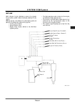
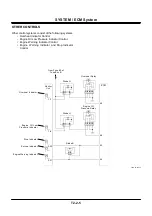
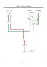
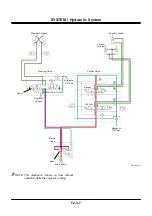
OUTLINE
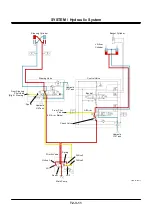
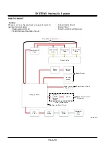
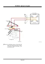
Hydraulic system is broadly be divided into the main
circuit, pilot circuit, steering circuit and hydraulic drive
fan circuit.
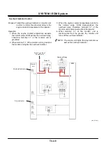
•
Main Circuit
Main circuit consists of the priority valve circuit,
neutral circuit, single operation circuit and
combined operation circuit – composed of the
main pump, priority valve, control valve, cylinders,
etc.
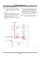
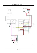
•
Pilot Circuit
Pilot circuit consists of the charging block circuit,
front attachment operation circuit, pump control
circuit, brake circuit and ride control circuit
(optional) – composed of the pilot pump, charging
block and valves to control each circuit.
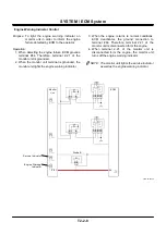
•
Steering Circuit
Steering circuit consists of the normal steering
circuit, steering shockless circuit, emergency
steering circuit (optional), steering stop circuit –
composed of the pump, priority valve, steering
valve, cylinders and other valves.
•
Hydraulic Drive Fan Circuit
Hydraulic drive fan circuit consists of the flow
control circuit and reverse rotation control circuit –
composed of the hydraulic fan motor and the fan
pump.
NOTE: Steering circuit can be divided into the main
circuit and the pilot circuit. It is described
here as an independent circuit.
Summary of Contents for ZW180
Page 1: ......
Page 2: ......
Page 8: ...4GDT 1 2 Blank ...
Page 10: ...GENERAL Specification T1 1 2 Blank ...
Page 38: ...GENERAL Component Specifications T1 3 14 Blank ...
Page 39: ...MEMO ...
Page 40: ...MEMO ...
Page 42: ...4GDT 2 2 Blank ...
Page 56: ...SYSTEM Control System T2 1 14 Blank ...
Page 82: ...SYSTEM Control System T2 1 40 Blank ...
Page 92: ...SYSTEM Control System T2 1 50 Blank ...
Page 106: ...SYSTEM Control System T2 1 64 Blank ...
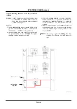
Page 116: ...SYSTEM ECM System T2 2 10 Blank ...
Page 128: ...SYSTEM Hydraulic System T2 3 12 Blank ...
Page 147: ...SYSTEM Hydraulic System T2 3 31 Blank ...
Page 150: ...SYSTEM Hydraulic System T2 3 34 Blank ...
Page 184: ...SYSTEM Electric System T2 4 34 Blank ...
Page 185: ...MEMO ...
Page 186: ...MEMO ...
Page 195: ...COMPONENT OPERATION Pump Device T3 1 7 Blank ...
Page 212: ...COMPONENT OPERATION Control Valve T3 2 4 T4GB 03 02 003 1 2 3 4 5 7 8 9 10 11 7 6 ...
Page 214: ...COMPONENT OPERATION Control Valve T3 2 6 T4GB 03 02 003 1 2 3 4 5 7 8 9 10 11 7 6 ...
Page 226: ...COMPONENT OPERATION Control Valve T3 2 18 Blank ...
Page 232: ...COMPONENT OPERATION Control Valve T3 2 24 Blank ...
Page 248: ...COMPONENT OPERATION Steering Pilot Valve T3 4 6 Blank ...
Page 258: ...COMPONENT OPERATION Steering Valve T3 5 10 Blank ...
Page 274: ...COMPONENT OPERATION Pilot Valve T3 6 16 Blank ...
Page 282: ...COMPONENT OPERATION Pilot Valve T3 6 24 Blank ...
Page 299: ...COMPONENT OPERATION Ride Control Valve T3 8 5 Blank ...
Page 306: ...COMPONENT OPERATION Ride Control Valve T3 8 12 Blank ...
Page 348: ...COMPONENT OPERATION Drive Unit T3 9 42 Blank ...
Page 371: ...MEMO ...
Page 372: ...MEMO ...
Page 374: ......


