


SYSTEM / Hydraulic System
T2-3-4
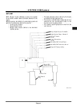
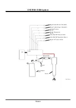
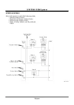
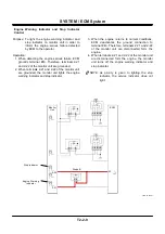
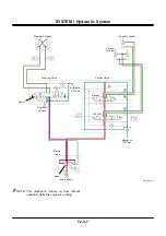
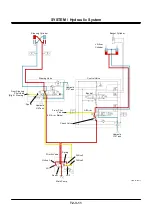
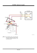
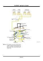
Priority Valve Circuit
•
At stop of the engine, the priority valve spool is
pushed leftward by the spring force.
•
When the engine is started, pressure oil from the
main pump flows to the steering valve through the
priority valve spool, and also flows to ports LS1
and LS2 through orifices 1 and 2 respectively.
•
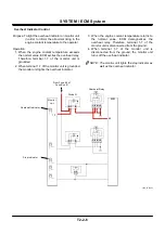
At neutral of the steering valve, as pressure oil to
port LS2 flows to the hydraulic oil tank through
orifice 3 and the steering valve spool, port LS2 is
not pressurized.
•
As pressure at port LS1 is larger than the spring
force, the priority valve spool moves rightward,
and all pressure oil from the main pump is
supplied to the control valve.
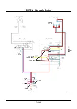
•
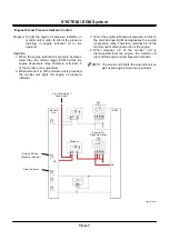
The priority valve spool is provided with a notch to
lead pressure oil from the main pump to the
steering valve and a notch to lead pressure oil
from the main pump to the control valve, which
are both connected to the main pump delivery
port constantly.
•
When the priority valve spool moves rightward,
the notch to lead pressure oil from the main pump
to the steering valve moves until the delivery port
on the steering valve side in the priority valve is
closed. When pressure balance is obtained and
the spool stops moving.
•
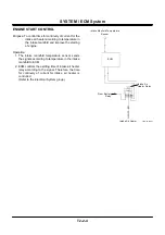
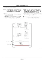
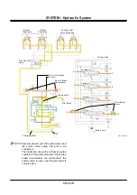
When the steering valve spool moves, the tank
port connected to port LS2 is closed.
•
At this time, as port LS2 is connected to the main
circuit through the steering valve spool, pressure
corresponding to movement of the steering valve
spool arises at port LS2.
•
When pressure at port LS2 and the spring force
overcome pressure at port LS1, the priority valve
spool moves leftward.
•
Larger the movement of the steering valve spool
is, the higher the pressure at port LS2 rises, the
larger the priority valve spool moves leftward, and
the more pressure oil from the main pump is
supplied to the steering valve.
NOTE: Orifice 2 of the priority valve is installed in
order to warm up the circuit by flowing
pressure oil to the hydraulic oil tank from
port LS2 at neutral of the steering valve.
Although diameter of port 2 is small and
temperature of the oil passing through it
rises rapidly, pressure is not raised enough
to influence movement of the priority valve
spool.
Summary of Contents for ZW180
Page 1: ......
Page 2: ......
Page 8: ...4GDT 1 2 Blank ...
Page 10: ...GENERAL Specification T1 1 2 Blank ...
Page 38: ...GENERAL Component Specifications T1 3 14 Blank ...
Page 39: ...MEMO ...
Page 40: ...MEMO ...
Page 42: ...4GDT 2 2 Blank ...
Page 56: ...SYSTEM Control System T2 1 14 Blank ...
Page 82: ...SYSTEM Control System T2 1 40 Blank ...
Page 92: ...SYSTEM Control System T2 1 50 Blank ...
Page 106: ...SYSTEM Control System T2 1 64 Blank ...
Page 116: ...SYSTEM ECM System T2 2 10 Blank ...
Page 128: ...SYSTEM Hydraulic System T2 3 12 Blank ...
Page 147: ...SYSTEM Hydraulic System T2 3 31 Blank ...
Page 150: ...SYSTEM Hydraulic System T2 3 34 Blank ...
Page 184: ...SYSTEM Electric System T2 4 34 Blank ...
Page 185: ...MEMO ...
Page 186: ...MEMO ...
Page 195: ...COMPONENT OPERATION Pump Device T3 1 7 Blank ...
Page 212: ...COMPONENT OPERATION Control Valve T3 2 4 T4GB 03 02 003 1 2 3 4 5 7 8 9 10 11 7 6 ...
Page 214: ...COMPONENT OPERATION Control Valve T3 2 6 T4GB 03 02 003 1 2 3 4 5 7 8 9 10 11 7 6 ...
Page 226: ...COMPONENT OPERATION Control Valve T3 2 18 Blank ...
Page 232: ...COMPONENT OPERATION Control Valve T3 2 24 Blank ...
Page 248: ...COMPONENT OPERATION Steering Pilot Valve T3 4 6 Blank ...
Page 258: ...COMPONENT OPERATION Steering Valve T3 5 10 Blank ...
Page 274: ...COMPONENT OPERATION Pilot Valve T3 6 16 Blank ...
Page 282: ...COMPONENT OPERATION Pilot Valve T3 6 24 Blank ...
Page 299: ...COMPONENT OPERATION Ride Control Valve T3 8 5 Blank ...
Page 306: ...COMPONENT OPERATION Ride Control Valve T3 8 12 Blank ...
Page 348: ...COMPONENT OPERATION Drive Unit T3 9 42 Blank ...
Page 371: ...MEMO ...
Page 372: ...MEMO ...
Page 374: ......


