


SYSTEM / Hydraulic System
T2-3-14
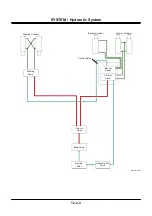
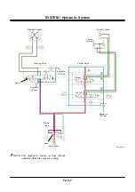
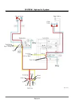
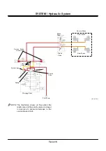
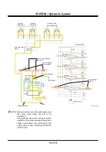
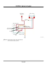
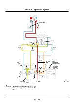
Charging Block Circuit
•
Charging block is installed in order to supply
pressure oil from the pilot pump preferentially to
the service brake circuit and distribute to other
pilot circuits as well.
•
When the engine is started, oil from the pilot
pump is delivered to the charging block.
•
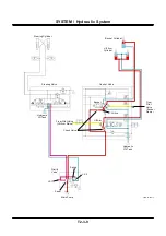
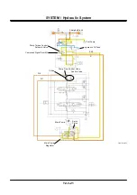
At this time, when the amount of accumulated
pressure of the service brake accumulators is low,
the relief valve is closed.
•
In this case, only pilot pressure is applied to port
B of the priority valve. As both pilot pressure and
the spring force are applied to port A, the priority
valve moves rightward and controls pressure oil
to flow further.
•
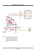
Pressure oil from the pilot pump flows to the
service brake circuit through the check valve, and
accumulates the service brake accumulators.
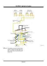
(To be continued to T2-3-16)
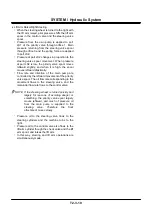
NOTE: The spring of the priority valve is adjusted
so that the priority valve is not completely
closed. Although the priority valve is closed
completely, a certain amount of pressure oil
is being supplied to the circuits
downstream.
Summary of Contents for ZW180
Page 1: ......
Page 2: ......
Page 8: ...4GDT 1 2 Blank ...
Page 10: ...GENERAL Specification T1 1 2 Blank ...
Page 38: ...GENERAL Component Specifications T1 3 14 Blank ...
Page 39: ...MEMO ...
Page 40: ...MEMO ...
Page 42: ...4GDT 2 2 Blank ...
Page 56: ...SYSTEM Control System T2 1 14 Blank ...
Page 82: ...SYSTEM Control System T2 1 40 Blank ...
Page 92: ...SYSTEM Control System T2 1 50 Blank ...
Page 106: ...SYSTEM Control System T2 1 64 Blank ...
Page 116: ...SYSTEM ECM System T2 2 10 Blank ...
Page 128: ...SYSTEM Hydraulic System T2 3 12 Blank ...
Page 147: ...SYSTEM Hydraulic System T2 3 31 Blank ...
Page 150: ...SYSTEM Hydraulic System T2 3 34 Blank ...
Page 184: ...SYSTEM Electric System T2 4 34 Blank ...
Page 185: ...MEMO ...
Page 186: ...MEMO ...
Page 195: ...COMPONENT OPERATION Pump Device T3 1 7 Blank ...
Page 212: ...COMPONENT OPERATION Control Valve T3 2 4 T4GB 03 02 003 1 2 3 4 5 7 8 9 10 11 7 6 ...
Page 214: ...COMPONENT OPERATION Control Valve T3 2 6 T4GB 03 02 003 1 2 3 4 5 7 8 9 10 11 7 6 ...
Page 226: ...COMPONENT OPERATION Control Valve T3 2 18 Blank ...
Page 232: ...COMPONENT OPERATION Control Valve T3 2 24 Blank ...
Page 248: ...COMPONENT OPERATION Steering Pilot Valve T3 4 6 Blank ...
Page 258: ...COMPONENT OPERATION Steering Valve T3 5 10 Blank ...
Page 274: ...COMPONENT OPERATION Pilot Valve T3 6 16 Blank ...
Page 282: ...COMPONENT OPERATION Pilot Valve T3 6 24 Blank ...
Page 299: ...COMPONENT OPERATION Ride Control Valve T3 8 5 Blank ...
Page 306: ...COMPONENT OPERATION Ride Control Valve T3 8 12 Blank ...
Page 348: ...COMPONENT OPERATION Drive Unit T3 9 42 Blank ...
Page 371: ...MEMO ...
Page 372: ...MEMO ...
Page 374: ......


