


COMPONENT OPERATION / Steering Valve
T3-5-8
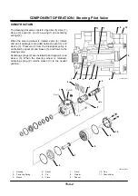
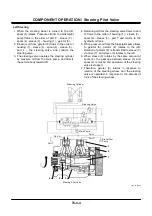
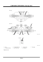
STEERING OVERLOAD RELIEF VALVE
The steering overload relief valve is installed in the left
and right steering circuits. The overload relief valve
controls pressure in the respective steering circuits
from rising abnormally high when the steering cylinder
is moved by an external force.
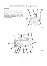
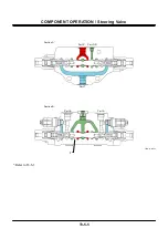
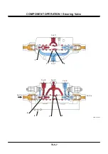
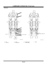
Relief Operation
1. Pressure at port HP (steering cylinder circuit) acts
on the pilot poppet through the orifice in the
piston.
2. When pressure at port HP reaches the set force of
spring B, the pilot poppet opens. Pressure oil
flows to port LP (hydraulic oil tank) through
passage A and the periphery of the sleeve.
3. At this time, pressure difference arises between
port HP and the spring chamber by the orifice.
4. When this pressure difference reaches the set
force of spring A, the piston and the main poppet
open, and pressure oil at port HP flows to port LP.
5. Consequently, pressure in the steering cylinder
circuit decreases.
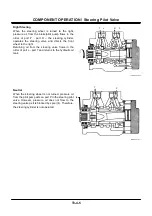
6. If pressure in the steering cylinder circuit
decreases to the set pressure value, the piston
and the main poppet are closed by the force of
spring A.
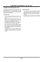
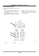
Make-Up Operation
1. When pressure at port HP (steering cylinder
circuit) becomes lower than pressure at port LP
(hydraulic oil tank), the sleeve moves to the right.
2. Hydraulic oil flows into port HP and cavitation is
prevented.
3. If pressure at port HP rises to the set pressure
value, the sleeve is closed by the force of spring
C.
Summary of Contents for ZW180
Page 1: ......
Page 2: ......
Page 8: ...4GDT 1 2 Blank ...
Page 10: ...GENERAL Specification T1 1 2 Blank ...
Page 38: ...GENERAL Component Specifications T1 3 14 Blank ...
Page 39: ...MEMO ...
Page 40: ...MEMO ...
Page 42: ...4GDT 2 2 Blank ...
Page 56: ...SYSTEM Control System T2 1 14 Blank ...
Page 82: ...SYSTEM Control System T2 1 40 Blank ...
Page 92: ...SYSTEM Control System T2 1 50 Blank ...
Page 106: ...SYSTEM Control System T2 1 64 Blank ...
Page 116: ...SYSTEM ECM System T2 2 10 Blank ...
Page 128: ...SYSTEM Hydraulic System T2 3 12 Blank ...
Page 147: ...SYSTEM Hydraulic System T2 3 31 Blank ...
Page 150: ...SYSTEM Hydraulic System T2 3 34 Blank ...
Page 184: ...SYSTEM Electric System T2 4 34 Blank ...
Page 185: ...MEMO ...
Page 186: ...MEMO ...
Page 195: ...COMPONENT OPERATION Pump Device T3 1 7 Blank ...
Page 212: ...COMPONENT OPERATION Control Valve T3 2 4 T4GB 03 02 003 1 2 3 4 5 7 8 9 10 11 7 6 ...
Page 214: ...COMPONENT OPERATION Control Valve T3 2 6 T4GB 03 02 003 1 2 3 4 5 7 8 9 10 11 7 6 ...
Page 226: ...COMPONENT OPERATION Control Valve T3 2 18 Blank ...
Page 232: ...COMPONENT OPERATION Control Valve T3 2 24 Blank ...
Page 248: ...COMPONENT OPERATION Steering Pilot Valve T3 4 6 Blank ...
Page 258: ...COMPONENT OPERATION Steering Valve T3 5 10 Blank ...
Page 274: ...COMPONENT OPERATION Pilot Valve T3 6 16 Blank ...
Page 282: ...COMPONENT OPERATION Pilot Valve T3 6 24 Blank ...
Page 299: ...COMPONENT OPERATION Ride Control Valve T3 8 5 Blank ...
Page 306: ...COMPONENT OPERATION Ride Control Valve T3 8 12 Blank ...
Page 348: ...COMPONENT OPERATION Drive Unit T3 9 42 Blank ...
Page 371: ...MEMO ...
Page 372: ...MEMO ...
Page 374: ......


