4
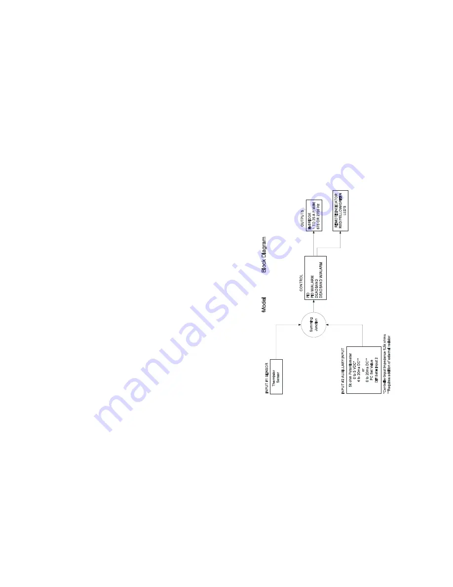
13. Now, click on the CONTROL TYPE menu key and select which type is appropriate for your application. The
DEADBAND CONTROL is an on/off control and PID CONTROL is a proportional/integral/derivative control. The
COMPUTER CONTROL acts like an electronic variac in that a fixed percentage of power may be applied to the load.
14. Clicking on the CONTROL MODE menu key permits the selection of either HEAT WP1+ and WP2- or HEAT WP2+
and WP1-. This selection establishes the polarity for the heating mode of the thermoelectric module. (i.e. If the
positive side of the module is connected to WP1 and the negative side to WP2, the module will heat when power is
applied to the module, and vice versa if the wiring is reversed.) This selection allows you to reverse the current flow
in the thermoelectric module without changing the wiring.
15. The ALARM TYPE setting permits the selection of available alarm options with this controller. The drop down
menu allows for four selections. NO ALARM PICKED indicates that no alarm parameters are desired. SET
TRACKING ALARMS allows an alarm to be set with respect to the set temperature and will move, accordingly, with
a change of the temperature setting. This option can be used for a high alarm, low alarm, or both settings. FIXED
VALUE ALARMS permits the setting of a fixed, absolute temperature either above or below the set point temperature
or both. COMPUTER CONTROLLED ALARM is not an actual alarm, but a user activation of the alarm relay via the
PC.
16. The POWER OUT SHUT DOWN IF ALARM menu key provides two selections. NO SHUT DOWN IF ALARM
which will let the power output stage of the controller to continue to function or MAIN OUT SHUTDOWN IF
ALARM which disables the power output stage under an alarm condition.
17. Associated with the ALARM TYPE configuration are the HIGH ALARM SETTING, LOW ALARM SETTING, and
the ALARM DEADBAND selections. If an alarm type has been selected, enter the desired high and low temperature
values. The ALARM DEADBAND option is to set the hysteresis of the alarm values from 0.1°F. to 100°F.
18. The ALARM LATCH option permits the selection of an ALARM LATCH OFF where the controller will automatically
reset if the alarm condition is self-correcting or ALARM LATCH ON which will maintain that an alarm condition
existed and must be manually cleared.
19. The CHOOSE SENSOR FOR ALARM option allows for the selection of either the thermistor CONTROL SENSOR or
the INPUT 2 SENSOR be used for the alarm.
20. The CHOOSE DEG C OR DEG F menu key permits the selection of displaying DEG F or DEG C.
21. Review all of your controller configuration selections. If all the configuration selections are correct for your
application, select the Send Box Values button to download these settings to the controller.
22. You are now ready to tune the controller. All selections for this portion will occur in the menu tree TUNING box
displayed on the monitor.
23. The various constants required by the controller to optimize the system performance are entered in this section.
11
TC
-1
36
TS
67
a
t -
2
0°
C
t
o
1
0
0°
C
TS
14
1
at
-
40
°C
t
o
7
0°
C

