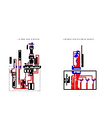
RS232 COMMUNICATIONS CONNECTIONS
FOR MODEL TC-136
JP3
1 2 3
RS232
TX
RX
COMMON
PC CONNECTION TABEL
PC CONNECTOR PC FUNCTION* CONTROLLER
9 PIN 25 PIN
PIN 2 3 RECIVE (RX) TRANSMIT (TX)
PIN 3 2 TRANSMIT (TX) RECEIVE (RX)
PIN 5 7 COMMON SHIELD
*Functions normally assigned to pins.
Check your PC manual to confirm.
RX
TX
SHLD
5
SET-UP INSTRUCTIONS FOR MODEL TC-136, THERMOELECTRIC MODULE,
PC PROGRAMMABLE, TEMPERATURE CONTROLLER
1.
Connect the appropriate DC power (12 to 28 volts) to the controller between WP3 (+) and WP4 (-) and the
thermoelectric module between WP1 and WP2 in accordance with the customer hook-up drawing. Note: the DC
power supply must also match the voltage and current ratings of the thermoelectric module configuration.
(Reference Application Note 351).
2.
Connect the RS232 Communications Port from the controller (JP3) to the RS232 input on the PC. Pin 1 of JP3 is the
controller’s RX, Pin 2 of JP3 is the controller’s TX, and Pin 3 of JP3 is the controller’s Shield.
3.
Turn power on to both the PC and controller. The on-board green LED will flash at a steady rate to indicate the
controller is energized correctly.
4.
Insert the TC-136 software disk into the computer A:\ drive. To install the software from the floppy disk, select
“START”, “RUN” from your Windows Desktop and then enter A:\Oi362.exe and OK. This will load the PC interface
into your computer’s RAM.
5.
NOTE: Refer to the Model TC-136 Menu Tree in this manual for factory default settings.
6.
The Menu Tree screen will appear on your PC monitor.
7.
NOTE: If you receive an error message, please refer to Appendix A.
8.
All selections are made from this menu screen. In the PC COMMUNICATIONS box, select the “COMM PORT” (1
through 4) which will be your communications link to the controller. After making this selection, click on the
INITIALIZE button.
9.
In the CONFIGURE box, the various menu selections are used to establish the custom operating criteria for the
controller. NOTE: To avoid damage to the thermoelectric module, confirm that the OUTPUT ON/OFF is in the
OFF position prior to proceeding!!
10. First, click on the PWM OUTPUT TIMEBASE (pulse width modulated) menu key, options for “SLOW TIMEBASE
675Hz” or “FAST TIMEBASE 2700Hz” will appear. Select the option that is appropriate for your thermoelectric
module(s).
11. Next, click on the SET TEMP TYPE INPUT 2 menu key to reveal the options available. COMPUTER SET VALUE is
to be set for the desired control set temperature. The other selections, POTENTIOMETER SET, 0 to 5 vdc SET, and
0 to 20 ma SET, are for external set temperature adjustments. The controller default setting for these options is the
full range of the thermistor input sensor. The DIFF.SET=INP2+COMPSET establishes an actual set temperature that
is the sum of the optional thermistor input sensor and the temperature selected as the COMPUTER SET VALUE.
12. Associated with the external set temperature adjustments are the SET TEMP HIGH RANGE and SET TEMP LOW
RANGE selections. These permit the selection of limitations on the temperature range of the external adjustments.
Enter the desired values for these settings. These set limit values must be within the -20°C. and 100°C. range
specified for the controller.
10

