
IOM_FCW-FCCW_10a120_207995_181001_EN
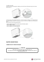
Connect the water inlet and outlet pipes, observing the indications given on the side of the appliance.
Correctly insulate the water supply pipes to prevent dripping during the cooling mode of operation. A
shutoff valve should be inserted on the water supply pipe and balancing valve on the outlet pipe. The valve
body and balancing valve should also be p
roperly insulated to prevent dripping. It is the installer’s
responsibility to insulate properly and the manufacturer cannot be held liable for any insulation work.
NOTE:
It is always advisable to install the solenoid valve. In the heating mode of operation the solenoid
valve reduces consumption because upon reaching the set temperature the circulation of water is
stopped to avoid wasting energy (the fan coil would otherwise continue to heat like a radiator, even
with the motor at a standstill). In the cooling mode of operation the solenoid valve stops the
circulation of water when the set temperature is reached, this stopping the internal exchanger from
continuing to condense water with possible undesirable dripping into the floor. It also reduces
chiller operation with consequent energy savings.
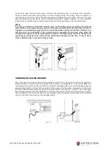
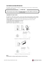
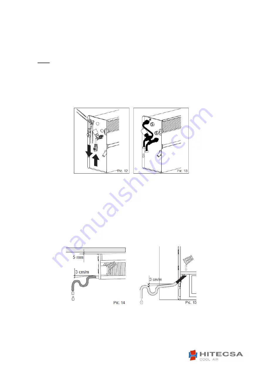
CONDENSATE WATER DRAINGE
The condensate drain pipe should slope downwards by at least 3 cm/m and should not have ascending or
throttled section in order to ensure a regular flow of water. It is advisable for a trap to be fitted. The
condensate drain pipe should be connected to a rainwater drainage system. Do not use sewage system to
avoid possible smells in the event of evaporation of the water in the trap. Upon completion of work, check
that the condensate flows out properly by pouring water into the tray (see Pic. 14 and 15). The condensate
water drainage system should be fabricated in a workmanlike manner and should be periodically checked.
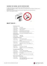
The manufacturer cannot be held liable for any damage caused by dripping in the absence of a solenoid
valve or of periodic maintenance of the drainage system.


