

IOM_FCW-FCCW_10a120_207995_181001_EN
Failure to comply with the indicated connections may cause motor burnout!
ATTENTION!
ELECTRICAL CONNECTIONS
Before carrying out electrical connections, ensure that the electricity supply to the supply line has been cut
off, checking that the on-off switch is in the OFF position. Only qualified electricians should carry out the
electrical connections.
Check that the mains supply is single-phase 230 Vac/1/50 Hz (± 10%).
Operating the appliance with voltages outside the above limits could cause malfunction and renders the
warranty null and void.
The fan coil power supply line should be fitted with at least a switch isolator in conformity with European
standard EN60947-3. Make sure that the electrical system is suitable for providing not only the working
current required by the appliance, but also the necessary current for powering household and other
electrical appliances already in use.
Any electrical and mechanical alterations or tampering render the warranty null and void. The motor and
accessories power cables in channels or ducts should remain inside the same until they are inside the
appliances.
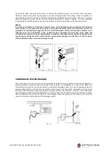
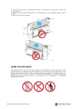
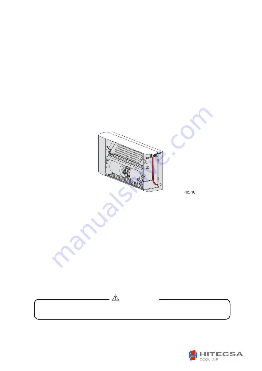
The cables should be sufficiently long so that they are not permanently taut or create throttling or pressure
on metal parts (see Pic. 16). The power cables should be sufficiently long so that in the event of accidental
tugging the active wires are subjected to stress before the earth wire. Connect the earth wire to the relative
terminal marked with the symbol.
Check the earth connection. Comply with the safety regulations in force in the country of installation
.
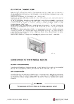
CONNECTIONS TO THE TERMINAL BLOCKS
WITHOUT CONTROL PANEL
The electrical connections should be made to the terminal block on the side of the appliance
(Pic. 17). Each terminal is identified by the label to be found on the terminal block.
WITH CONTROL PANEL
The electrical connections should be made directly to the control panel, as shown by the relative
wiring diagram. If the control panel has an electronic temperature sensor (NTC) this sensor will
be powered by mains voltage (230Vac/1/50 Hz) and is therefore provided with double
insulation.


