64
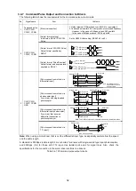
Command Pulse Output and Connection to Drivers
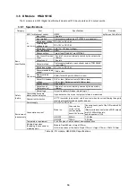
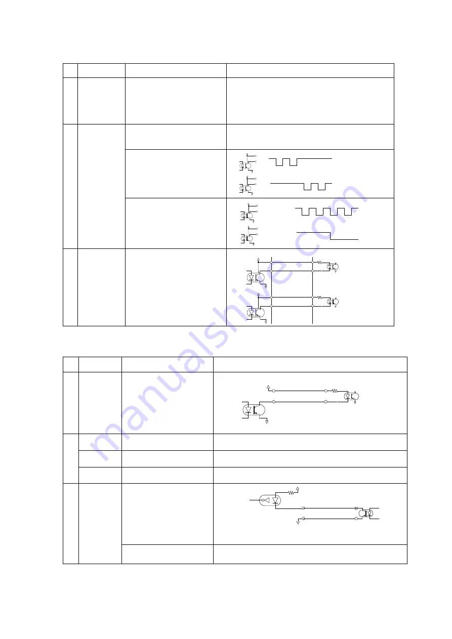
The following table shows the requirements for the command pulse output circuits.
No.
Signals
involved
Item
Contents
1
Command
pulse
CWP
CCW
[Electrical condition]
1. Output element: High-speed photocoupler (TLP115A or
equivalent)
2. Command pulse width: 50% duty width of command
frequency
However, in the case of 2.4Kpps or less: 200
μs width
In the case of 5Mpps or above: 30% duty width
2
CW
CCWP,
CCWN
[Output format setting]
Initial value: RENV1 CW/CCW
Pulse
Set by G9003 initial setting (RENV1-b2 to b0)
[Output format: CW/CCW Pulse]
Output format specified by
RENV1.
[Output format: Pulse/Direction]
Output format and direction level
specified by RENV1.
3
CW
CCW
[Driver connection method]
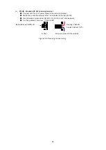
Table 3.5-6 Command pulse output circuit
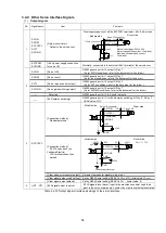
3.5.5 Driver Control Signal
No.
Signals
involved
Item
Contents
1
MF,
C/S,
CD_INH
[Output circuit form]
Output to driver
2
MF
[Excitation OFF output]
G9003 generic port bit 0: output ON by ‘1’
(As for MF conditions, refer to the document for the driver.)
C/S
[Step angle switching output]
G9003 generic port bit 2: output ON
by ‘1’
(As for C/S conditions, refer to the document for the driver.)
CD_INH
[Forced automatic
current-down prohibition]
G9003 generic port bit 3: output ON by ‘1’
(As for CD_INH conditions, refer to the document for the driver.)
3
TIM
[Input circuit form]
Timing input
* TIM is input to Z-phase.
[Z-phase input signal polarity
switching]
Set by G9003 initial setting (RENV2-b11) (Initial value: + pulse)
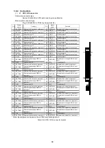
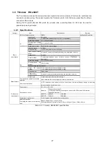
Table 3.5-7 Driver control signal circuits
GN
D
5V
5V 出力
CW
GND
5V
5V 出力
CCW
パルス列信号
方向切替信号
GN
D
5V
5V 出力
CW
GND
5V
5V 出力
CCW
GND
5V
5V 出力
CW
GND
5V
5V 出力
CCW
GND
5V
5V 出力
MF,C/S,CD_INH
5V
GND
Z
TIM
GND
TLP115相当
Module side
Driver side
Module side
Driver side
TLP281 or equivalent
Driver I/F connector
Module side
Driver side
5V output
5V output
5V output
5V output
5V output
5V output
Pulse-train signal
TLP115 or equivalent
5V output
Direction switching signal
Summary of Contents for motionCAT HCPCI-MNT720M
Page 3: ......
Page 12: ...1 Warnings and Precautions...
Page 20: ...9 1 motionCAT Installation...
Page 109: ...98 4 Installation Guide...
Page 118: ...107 5 Device Driver Installation...
Page 122: ...111 6 Trial Operation...
Page 145: ...134 7 Accessories...
Page 147: ...136 8 Glossary...
Page 161: ...150 9 Connections to Drivers Supplied by Manufacturers...


