80
3.9.4 Connector Terminal Electrical Requirements
24 among the 30 input points, that is, excluding those for the origin sensors can be used for general-purpose
input/output.
Switching by software is required to use as general-purpose input/output.
Points
Switching to
general-purpose
Allowable
current
Input
24
Possible
---
Common use with +ELS, -ELS, DLS sensors of 6 axes.
6
Not possible
---
OLS sensors of 6 axes.
Output
8
General-purpose only
100mA/point
Table 3.9-3 Connector terminal electrical requirements
3.9.5 Input Circuit
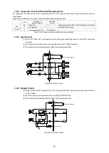
(1) DC +12V to DC +24V is supplied from the receiving terminals as power for the DI I/F. 5V cannot
be used.
(2) The power for the sensors can be provided from the DI_POW terminals.
(3) The fuses are located immediately after the receiving terminals.
Figure 3.9-2 Input circuit
3.9.6 Output Circuit
(1) Power for the DO I/F is supplied from the receiving terminals . The same power supply as for the
DI I/F is used.
(2) The load power can be provided from the DO_POW terminals.
(3) The fuses are located immediately after the receiving terminals.
Figure 3.9-3 Output circuit
IN_01
GND
P24-IN
GND
680
Ω
1.8K
Ω
1.8K
Ω
Fuse
DI_POW
IN_24
680
Ω
1.8K
Ω
+24V
電源
1.8K
Ω
TD62084
33K
Ω
10
Ω
DO_POW
P24-IN
GND
Fuse
+24V
電源
負荷
OUT-01
OUT-32
負荷
10
Ω
GND (A26,B26)
33K
Ω
Fuse
GND
+24V power supply
+24V power supply
Load
Load
Summary of Contents for motionCAT HCPCI-MNT720M
Page 3: ......
Page 12: ...1 Warnings and Precautions...
Page 20: ...9 1 motionCAT Installation...
Page 109: ...98 4 Installation Guide...
Page 118: ...107 5 Device Driver Installation...
Page 122: ...111 6 Trial Operation...
Page 145: ...134 7 Accessories...
Page 147: ...136 8 Glossary...
Page 161: ...150 9 Connections to Drivers Supplied by Manufacturers...

