81
3.10 A Module HM-A4401C
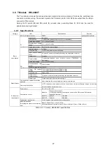
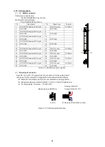
The A module is an analog, voltage input/output module with 4 input points and 4 output points.
3.10.1 Specifications
Category
Item
Specifications
Remarks
Basic
specification
ASIC for Motionnet control
G9002
by Nippon Pulse Motor
Input mode
Input count
4 points
Input voltage
0 to +10V
Resolution
12 bits
Output mode
Output count
4 points
Output voltage
0 to +10V (5mA Max.)
Load impedance 2k
or more
Resolution
12 bits
Function
specifications
Refresh cycle
A/D value, D/A value, and status are refreshed every 0.4ms
D/A value output
Manual output, preset output, automatic output by profile
Automatic output by D/A profile Automatic output of D/A values based on up to 15 points of
T (time) and voltage set in advance (preset).
A/D comparator
Upper and lower limits for comparison can be set for each channel. The result of the comparison is output
as status.
Safety feature
Communication cable
disconnection detection
Upon detection, the output voltage is maintained
Overcurrent protection
A PTC thermistor (poly switch) cuts the current when the current flowing through its receiving terminal
exceeds a certain amount.
Environment
requirements
Power supply
DC +12V to DC +24V
Consumption current
Model no.
Consumption current
of the communication
board 24V terminal
Consumption current of the module’s 24V power supply terminal
(Maximum load current when all outputs and inputs are at the
maximum (10V))
HMG-A1
1.5A
2.3A Max.
HMG-A2
2.1A
3.7A Max.
Temperature requirement
0 to 50 degrees Celsius without dew condensation
Module dimensions
(Excluding the connector’s
projecting part)
Module: Depth 85mm × Height 105mm
Outer dimensions of the frame: Depth 110mm × Height 115mm × Width 14.2mm
Table 3.10-1 A module, HM-A4401C specifications
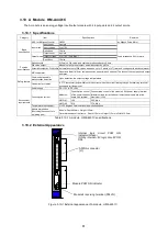
3.10.2 External Appearance
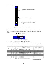
Figure 3.10-1 External appearance of A module, HM-A4401C
AD/DA connector
(J1)
Module's receiving terminal (P24-IN)
Module POW ON indicator
Internal
logic
circuit
POW
ON
indicator (Green)
(ON by in5V logic circuit POW
ON)
Summary of Contents for motionCAT HCPCI-MNT720M
Page 3: ......
Page 12: ...1 Warnings and Precautions...
Page 20: ...9 1 motionCAT Installation...
Page 109: ...98 4 Installation Guide...
Page 118: ...107 5 Device Driver Installation...
Page 122: ...111 6 Trial Operation...
Page 145: ...134 7 Accessories...
Page 147: ...136 8 Glossary...
Page 161: ...150 9 Connections to Drivers Supplied by Manufacturers...


