82
3.10.3 Connectors
(1)
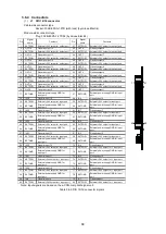
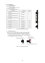
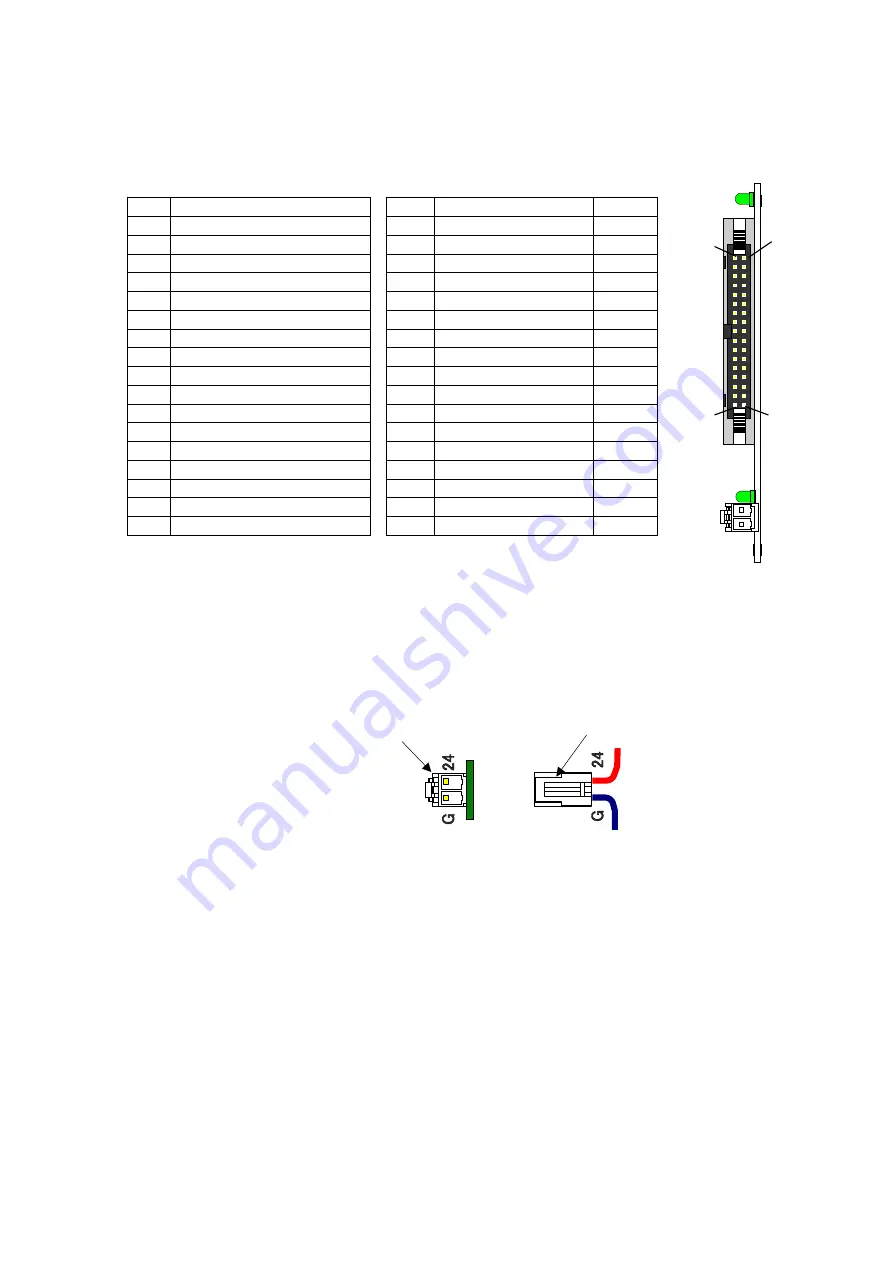
J1 AD/DA connector
Cable-side connector type
Socket: XG4M-3430-T (by Omron)
Module-side connector type
Plug: XG4A-3434 (by Omron)
Pin
Signal name
Pin
Signal name
Remarks
1
EXT-POW (Shared with DC input)
2
DA/-CH1 output
0 to 10V
3
EXT-GND
4
EXT-GND
5
EXT-POW (Shared with DC input)
6
DA/-CH2 output
0 to 10V
7
EXT-GND
8
EXT-GND
9
EXT-POW (Shared with DC input)
10
DA/-CH3 output
0 to 10V
11
EXT-GND
12
EXT-GND
13
EXT-POW (Shared with DC input)
14
DA/-CH4 output
0 to 10V
15
EXT-GND
16
EXT-GND
17
18
19
EXT-POW (Shared with DC input)
20
A/D-CH1 input
0 to 10V
21
EXT-GND
22
EXT-GND
23
EXT-POW (Shared with DC input)
24
A/D-CH2 input
0 to 10V
25
EXT-GND
26
EXT-GND
27
EXT-POW (Shared with DC input)
28
A/D-CH3 input
0 to 10V
29
EXT-GND
30
EXT-GND
31
EXT-POW (Shared with DC input)
32
A/D-CH4 input
0 to 10V
33
EXT-GND
34
EXT-GND
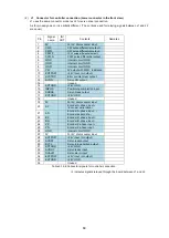
Table 3.10-2 AD/DA connector signals
(2)
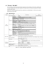
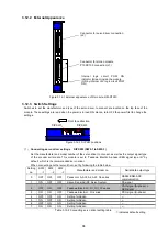
Power input connector
Input DC +12 to 24V. The power from this connector is for the analog circuit.
(The power for the internal IC is supplied from the communication module)
⚫
Match the connection polarity to the one indicated on the plug (24/G).
⚫
Recommended wire material: AWG20 - 18 (0.5 to 0.9mm
2
stranded wire)
⚫
For fixing cables: Crimp tool YC-630 (JST)
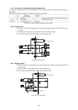
Figure 3.10-2 Receiving terminal wiring
Housing: VHR-2N
Contact: BVH-41T-P1.1
Board side post: B2PS-VH
1 2
33 34
A. Post
B. Housing (Fixed to the contact)
Summary of Contents for motionCAT HCPCI-MNT720M
Page 3: ......
Page 12: ...1 Warnings and Precautions...
Page 20: ...9 1 motionCAT Installation...
Page 109: ...98 4 Installation Guide...
Page 118: ...107 5 Device Driver Installation...
Page 122: ...111 6 Trial Operation...
Page 145: ...134 7 Accessories...
Page 147: ...136 8 Glossary...
Page 161: ...150 9 Connections to Drivers Supplied by Manufacturers...

