background image

Network Mini PT Dome Camera

·

Quick Start Guide


30 

30 

4


Accessing via Web Browser 

System Requirement: 

Operating System: Microsoft Windows XP SP1 and above version   

CPU: 2.0 GHz or higher 

RAM: 1G or higher 

Display: 1024×768 resolution or higher 

Web Browser: Internet Explorer 8.0 and above version, Apple Safari 
5.0.2 and above version, Mozilla Firefox 5.0 and above version and 
Google Chrome 18 and above version 

Steps: 

1.


Open the web browser. 

2.


In the browser address bar, input the IP address of the network 
camera, and press the 

Enter

 key to enter the login interface. 

Note: 


The default IP address is 192.168.1.64. You are recommended 
to change the IP address to the same subnet with your 
computer. 

3.


Input the user name and password. 

The admin user should configure the device accounts and 
user/operator permissions properly. Delete the unnecessary 
accounts and user/operator permissions. 

Note: 

The device IP address gets locked if the admin user performs 7 
failed password attempts (5 attempts for the user/operator). 

Summary of Contents for DS-I12Q

Page 1: ...1 Network Mini PT Dome Camera Quick Start Guide ...

Page 2: ...TO THE PRODUCT WITH INTERNET ACCESS THE USE OF PRODUCT SHALL BE WHOLLY AT YOUR OWN RISKS OUR COMPANY SHALL NOT TAKE ANY RESPONSIBILITES FOR ABNORMAL OPERATION PRIVACY LEAKAGE OR OTHER DAMAGES RESULTING FROM CYBER ATTACK HACKER ATTACK VIRUS INSPECTION OR OTHER INTERNET SECURITY RISKS HOWEVER OUR COMPANY WILL PROVIDE TIMELY TECHNICAL SUPPORT IF REQUIRED SURVEILLANCE LAWS VARY BY JURISDICTION PLEASE ...

Page 3: ...adio communications Operation of this equipment in a residential area is likely to cause harmful interference in which case the user will be required to correct the interference at his own expense FCC Conditions This device complies with part 15 of the FCC Rules Operation is subject to the following two conditions 1 This device may not cause harmful interference 2 This device must accept any inter...

Page 4: ...tion for specific battery information The battery is marked with this symbol which may include lettering to indicate cadmium Cd lead Pb or mercury Hg For proper recycling return the battery to your supplier or to a designated collection point For more information see www recyclethis info Industry Canada ICES 003 Compliance This device meets the CAN ICES 3 A NMB 3 A standards requirements Safety In...

Page 5: ...fer to technical specifications for detailed information Do not connect several devices to one power adapter as adapter overload may cause over heating or a fire hazard Please make sure that the plug is firmly connected to the power socket When the product is mounted on wall or ceiling the device shall be firmly fixed If smoke odor or noise rise from the device turn off the power at once and unplu...

Page 6: ...tect the sensor from dirt Do not aim the camera at the sun or extra bright places Blooming or smearing may occur otherwise which is not a malfunction and affect the endurance of sensor at the same time The sensor may be burned out by a laser beam so when any laser equipment is in using make sure that the surface of sensor will not be exposed to the laser beam Do not place the camera in extremely h...

Page 7: ...and using history so regular checking is recommended for all the users Please contact with your dealer for more details Improper use or replacement of the battery may result in hazard of explosion Replace with the same or equivalent type only Dispose of used batteries according to the instructions provided by the battery manufacturer If the product does not work properly please contact your dealer...

Page 8: ...24 3 2 Activation via Web Browser 24 3 2 1 Activation via SADP Software 25 3 2 2 Modifying the IP Address 27 3 3 4 Accessing via Web Browser 30 5 Operating via Guarding Vision App 32 Enable Guarding Vision Service on Camera 32 5 1 Enable Guarding Vision Service via SADP Software32 5 1 1 Enable Guarding Vision Service via Web Browser33 5 1 2 Guarding Vision Setup 35 5 2 Adding Camera to Guarding Vi...

Page 9: ...Appearance Description Overview 1 1 Two types of network Mini PT cameras are shown below Type I WiFi network transmission is supported for the Type I network Mini PT camera 1 2 3 4 Overview 1 Type I Figure 1 1 5 6 7 8 9 10 Overview 2 Type I Figure 1 2 ...

Page 10: ...e 1 3 Description of Type I Network Mini PT Camera Table 1 1 No Description 1 Silicone Gasket 2 Dome Drive 3 WPS Wi Fi Protected Setup Button 4 Micro SD Card Slot 5 Photic Cover 6 Lens 7 Lens Ring 8 PIR Passive Infrared sensor 9 MIC 10 Mounting Base 11 10M 100M self adaptive Ethernet interface ...

Page 11: ...rface 13 Reset 14 Audio Out 15 Power supply interface 5 VDC 16 Speaker 17 Status LED Solid blue Network is connected and camera is unarmed Flicking blue No network connection Solid red Camera is armed Flicking red Camera is not working properly Solid green Camera is connected to the platform ...

Page 12: ...he Type II network Mini PT camera 4G and Wi Fi network transmission are optional 1 2 3 4 Overview 1 Type II Figure 1 4 9 5 6 7 8 10 Overview 2 Type II Figure 1 5 For the Type II network Mini PT camera supporting the 4G network transmission the Wi Fi network transmission does not take effect ...

Page 13: ...ype II Figure 1 6 Description of Type II Network Mini PT Camera Table 1 2 No Description 1 Silicone Gasket 2 Dome Drive 3 4G SIM Card Slot optional 4 Micro SD Card Slot 5 Photic Cover 6 Lens 7 Lens Ring 8 PIR Passive Infrared sensor 9 MIC 10 Mounting Base 11 Alarm Input output Interface ...

Page 14: ... Status LED Solid blue Network is connected and camera is unarmed Flicking blue No network connection Solid red Camera is armed Flicking red Camera is not working properly Solid green Camera is connected to the platform and unarmed Solid yellow Camera is connected to the platform and armed The figures shown in this manual are for reference only The appearance and interfaces of the camera are subje...

Page 15: ... port No etc A wireless router with the WPS function is required to enable the WPS function of the camera Steps 1 Press the WPS button on the router 2 Press the WPS button about 2s on the camera within 120s you enable the WPS of the router to join in the wireless network Installing SD SIM Card 1 2 Steps Pull the removable cover on the mounting base outwards and 1 move it aside Insert the SIM card ...

Page 16: ... Dome Camera Quick Start Guide 16 SIM Card Micro SD Card Removable Cover Install SD SIM Card Figure 1 7 Remote Control 1 3 A remote control is supplied for the Type II network Mini PT camera Remote Control Figure 1 8 ...

Page 17: ...rm is enabled Disarm Button Press the button to disarm the camera In the disarming status the alarm linkage is disabled Emergency Button Long press the button for 2s to trigger the emergency alarm The emergency alarm has the highest priority Privacy Button Press the button to stop or start video stream sending When the video stream is stopped you can t see the live view or get the record stream on...

Page 18: ...he camera that supports IR you are required to pay attention to the following precautions to prevent IR reflection Dust or grease on the dome cover will cause IR reflection Please do not remove the dome cover film until the installation is finished If there is dust or grease on the dome cover clean the dome cover with clean soft cloth and isopropyl alcohol Make sure that there is no reflective sur...

Page 19: ...de 19 Steps Drill the screw holes on the ceiling according to the supplied drill 1 template Drill Template Figure 2 1 Align the screw holes on the ceiling and adapter plate and then 2 fix the adapter plate to the ceiling with the supplied screws ...

Page 20: ...r cement wall you need to use the expansion screw to fix the mount for wooden wall you can just use the self tapping screw to fix the mount Align the mounting base of the camera to the adapter plate and 3 rotate the camera clockwise until it is locked up by the three bayonet joints on the adapter plate ...

Page 21: ... LOCK Install the Camera Figure 2 3 Adjust surveillance view angle 4 1 Hold and rotate the main camera body to adjust the view angle in the pan direction 0 355 2 Move the dome drive upwards or downwards to adjust the view angle in the tilt direction 20 90 ...

Page 22: ...90 Camera Body Dome Drive Adjust the View Angle Figure 2 4 Table mounting is also available for the network Mini PT camera If the camera needs to be fixed on the table refer to the above steps described for the ceiling mounting if not just place the camera on the table ...

Page 23: ...k attacks and information leakage please strengthen your own protection If the product does not work properly contact your dealer or the nearest service center for help Wiring 3 1 Connect the camera to network according to the following figures 半球 Network Cable or Network Camera Computer Connecting Directly Figure 3 1 网络交换机 半球 Network Cable Network Cable or or Network Camera Computer Connecting vi...

Page 24: ...he camera activation Note Refer to the User Manual of Network Camera for Activation via Client Software Activation via Web Browser 3 2 1 Steps 1 Power on the camera Connect the camera to your computer or the switch router which your computer connects to 2 Input the IP address into the address bar of the web browser and press Enter to enter the activation interface Notes The default IP address of t...

Page 25: ...ase letters lower case letters numbers and special characters in order to increase the security of your product And we recommend you reset your password regularly especially in the high security system resetting the password monthly or weekly can better protect your product 4 Confirm the password 5 Click OK to save the password and enter the live view interface Activation via SADP Software 3 2 2 S...

Page 26: ...mera for other two activation methods Steps 1 Run the SADP software to search the online devices 2 Check the device status from the device list and select the inactive device Select inactive device Input and confirm password SADP Interface Figure 3 4 Note The SADP software supports activating the camera in batch Refer to the user manual of SADP software for details 3 Create and input the new passw...

Page 27: ... the device during activation Refer to Chapter 5 1 for detailed information 4 Click Activate to start activation You can check whether the activation is completed on the popup window If activation failed make sure that the password meets the requirement and try again Modifying the IP Address 3 3 Purpose To view and configure the camera via LAN Local Area Network you need to connect the network cam...

Page 28: ... 28 Steps 1 Run the SADP software 2 Select an activate device 3 Change the device IP address to the same subnet with your computer by either modifying the IP address manually or checking the checkbox of Enable DHCP Modify the IP Address Figure 3 5 ...

Page 29: ...ion service for the device during activation Refer to Chapter 5 1 for detailed information 4 Input the admin password and click Modify to activate your IP address modification The batch IP address modification is supported by the SADP Please refer to the User Manual of SADP for details ...

Page 30: ...on Steps 1 Open the web browser 2 In the browser address bar input the IP address of the network camera and press the Enter key to enter the login interface Note The default IP address is 192 168 1 64 You are recommended to change the IP address to the same subnet with your computer 3 Input the user name and password The admin user should configure the device accounts and user operator permissions...

Page 31: ...se follow the installation prompts to install the plug in Note You may have to close the web browser to finish the installation of the plug in Download Plug in Figure 4 2 6 Reopen the web browser after the installation of the plug in and repeat steps 2 to 4 to login Note For detailed instructions of further configuration please refer to the user manual of network camera ...

Page 32: ...ing Vision Service on Camera 5 1 Purpose Guarding Vision service should be enabled on your camera before using the service You can enable the service through SADP software or web browser Enable Guarding Vision Service via SADP Software 5 1 1 Steps 1 Check the checkbox of Enable Guarding Vision on 1 Activate the Device page during camera activation refer to Chapter 3 2 2 2 Or Modify Network Paramet...

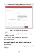
Page 33: ...1 Note The verification code is required when you add the camera to Guarding Vision app 3 Click and read Terms of Service and Privacy Policy 4 Confirm the settings Enable Guarding Vision Service via Web Browser 5 1 2 Before you start You need to activate the camera before enabling the service Refer to Chapter 3 2 ...

Page 34: ...s Guarding Vision dev guardingvision com Platform Access Configuration Web Figure 5 2 3 Select Platform Access Mode as Guarding Vision 4 Check the checkbox of Enable 5 Click and read Terms of Service and Privacy Policy in pop up window 6 Create a verification code or change the verification code for the camera Note The verification code is required when you add the camera to Guarding Vision app 7 ...

Page 35: ...ision 5 3 Before you start You need to enable the Guarding Vision service on camera before adding it to your Guarding Vision account Refer to Chapter 5 1 Steps 1 Use a network cable to connect the camera with a router if the camera does not support Wi Fi Figure 5 3 Connect a Router Note After the camera connects to the network please wait one minute before any operation on the camera using Guardin...

Page 36: ...e camera s serial number 3 Input the verification code of your camera Note The required verification code is the code you create or change when you enabling Guarding Vision service on camera If you forget the verification code you can check the current verification code on Platform Access configuration page via web browser 4 Follow the prompts to set the network connection and add the camera to yo...

Page 37: ... the memory card status by tapping on the Storage Status in the Device Settings interface If the memory card status displays as Uninitialized tap to initialize it The status will then change to Normal You can then start recording any event triggered video in the camera such as motion detection ...

Page 38: ...0 ...
Reviews: