22
C22UE001-2004
1.3
Connection with the Controller
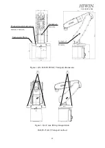
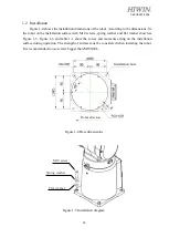
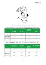
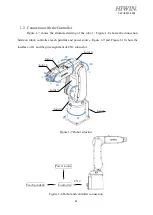
Figure 1-7 shows the structure drawing of the robot.
;
Figure 1-8 shows the connection
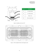
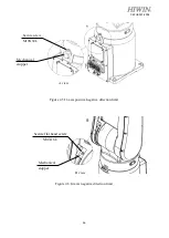
between robot, controller, teach pendant and power source. Figure 1-9 and Figure 1-10 show the
interface of J1 and the pin assignment of CN2 connector.
Figure 1-7 Robot structure
Figure 1-8 Robot and controller connection
Joint 1
Joint 4
Joint 5
+
-
J3
J4
+
-
Joint 6
Joint 2
Joint 3
J1
+
-
+
-
J2
+
-
J5
J6
+
-
CN2
Controller
Power source
Teach pendant


