39
C22UE001-2004
3.3
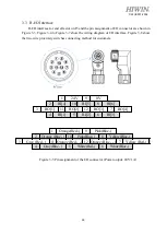
R-I/O Interface
R-I/O interface for end effector on J5 and the pin assignment of I/O connector are shown in
Figure 3-3. Figure 3-4 to Figure 3-7 show the wiring diagram of I/O interface. Figure 3-8 show
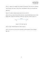
the two-wire proximity switches connecting method for customers.
Figure 3-3 Pin assignment of the I/O connector (Power output: 24V/1A)
1
9
2
10
8
3
11
12
7
4
5
6
White(Blue-)
Pink(Blue-)
Orange (Blue -)
Pink(Blue-)
Yellow(Blue-)
Gray (Red -)
Orange (Red - -)
Orange (Blue - -)
Yellow (Red-)
Orange(Red-)
Gray(Blue -)
White(Red-)
1
9
2
10
8
3
11
12
7
4
5
6
RO[2]
RO[3]
RO[4]
RI[1]
RI[2]
RI[3]
24V
0V
RI[4]
RI[5]
RI[6]
RO[1]


