21
C08UE001-1912
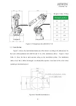
Figure 1-3Transport position (RA620-1739)
1.2
Installation
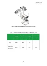
Figure 1-4 shows the installation dimensions of the robot. According to the dimensions, fix
the robot with installation bolt
(M16 Grade 12.9) on the installation surface. Figure 1-5 and
Table 1-1 show the forces and moments acting on the installation surface. The installation
surface must have sufficient strength to withstand the dynamic movement of the robot when
operating at maximum speed.
Figure1-4 Installation dimension
Transport position
J1
0°
J2
35°
J3
-70°
J4
0°
J5
-55°
J6
0°
Center of gravity
Center of gravity
Weight of robot: 230 kg
Summary of Contents for RA620-1621
Page 1: ...www hiwin tw User Manual Articulated Robot RA620 Original Instruction...
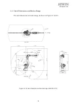
Page 35: ...34 C08UE001 1912 Figure 2 3 Outer dimension and motion range RA620 1621 J1 0 deg...
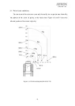
Page 37: ...36 C08UE001 1912 Figure 2 5 Wrist load diagram RA620 1621...
Page 54: ...53 C08UE001 1912 Table 5 3 Inspection schedule...


