24
C08UE001-1912
1.3
Connection with the Controller
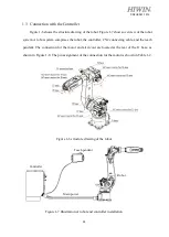
Figure 1-6 shows the structure drawing of the robot. Figure 1-7 shows overview of the robot
system. A robot system comprises the robot, the controller, CN2 connecting cable, and the teach
pendant. The connection for the motor and air in/out are located at the rear of the J1 base, as
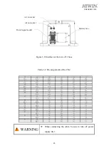
shown in Figure 1-8. The pin assignment of the connection for the motor is shown in Table 1-2.
Figure 1-6 structure drawing of the robot
Figure 1-7 Illustration of robot and controller installation
Teach pendant
Controller
Robot
Main power
Summary of Contents for RA620-1621
Page 1: ...www hiwin tw User Manual Articulated Robot RA620 Original Instruction...
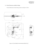
Page 35: ...34 C08UE001 1912 Figure 2 3 Outer dimension and motion range RA620 1621 J1 0 deg...
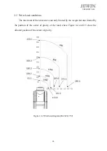
Page 37: ...36 C08UE001 1912 Figure 2 5 Wrist load diagram RA620 1621...
Page 54: ...53 C08UE001 1912 Table 5 3 Inspection schedule...


