57
C08UE001-1912
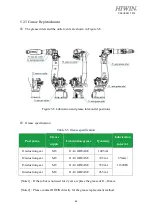
Removing the cover
Before replacing the belt, remove the cover of the J5 base. The M4
×
0.7P
×
15L screws are used,
as shown in Figure 5-3.
Figure 5-3 Remove the cover
Inspection, maintenance and replacement of timing belt in J5 -axis.
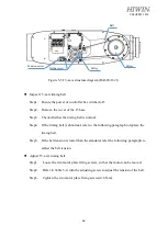
Figure 5-4 J5 -axis structure diagram (RA620-1739)
Pulley
Belt
Tension screw
Fixing screw
Pulley
Summary of Contents for RA620-1621
Page 1: ...www hiwin tw User Manual Articulated Robot RA620 Original Instruction...
Page 35: ...34 C08UE001 1912 Figure 2 3 Outer dimension and motion range RA620 1621 J1 0 deg...
Page 37: ...36 C08UE001 1912 Figure 2 5 Wrist load diagram RA620 1621...
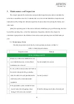
Page 54: ...53 C08UE001 1912 Table 5 3 Inspection schedule...

