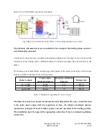
point of view of hydraulics layouts are acceptable.
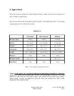
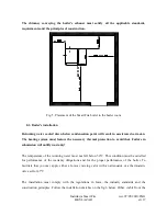
Fig.6 Sketch of connections of the boiler to the heating and tap water system
The hydraulic schemata herein are not substitute for a design of the heating system and serve
only information purposes!
You must also obey the rules concerning the minimum diameters of the pipes in the circuit and the
connectors of the mixing valves. Minimum diameters of the water pipes have been shown in the
table 3.
The heating system must feature an emptying outlet placed at the lowest point of the circuit and as
close as possible to the inlet of the returning water.
Boiler's output
Copper pipes,
minimum diameter
Steel pipes, minimum
diameter
Mixing valve
14 ÷ 29 kW
35 mm
1¼”
DN 32
30 ÷ 50 kW
42 mm
1½”
DN 40
oper 51 kW
50 mm
2”
DN 50
Table 3: Guidelines regarding the water circuits
The data above have been quoted for information only! Regardless, the water circuit attached
to the boiler must comply with the regulations in force, the industry standards and the
construction principles. It must facilitate proper and safe operation of the heating systems.
The installation must be inspected by appropriate authorities if local or national regulations
require this.
Instrukcja Smart Fire
wer. 07/05/2010/ENG
HKS LAZAR
str.18

