background image

 5  


SAFETY INSTRUCTIONS 

WORK SAFELY – A CAREFUL OPERATOR IS THE BEST INSURANCE AGAINST ACCIDENTS!!


WARNING SECTION [Continued] 


Hydraulic fluid under pressure can penetrate the skin 
and cause serious injury or death. Hydraulic leaks 

under pressure may not be visible! 


If any fluid penetrates the skin, GET IMMEDIATE 
MEDICAL ATTENTION!! 


Wear safety glasses, protective clothing and use a 
sound piece of cardboard or wood when searching for 
hydraulic leaks. DO NOT USE YOUR HANDS! 


Before connecting or disconnecting hydraulic hoses, 
read your tractor or power unit’s operator’s manual for 
detailed instructions on connecting and disconnecting 
hydraulic attachments. 


Make certain that all parts meet the specifications for 
this product when installing or replacing hydraulic 

hoses or fittings. 


After connecting hydraulic lines: 

  Slowly and carefully raise the loader and cycle the 

rollback / dump cylinders to check hose 
clearances and to check for any interference. 

  Operate the hydraulics on this product to check 

hose clearances and to check for any 
interference. 

  Make certain that the hoses cannot interfere with 

or actuate the quick-attach mechanism. 

  Make certain that hoses will not be pinched, or get 

tangled, in any equipment. 


Do not lock the auxiliary hydraulics of your power unit 
in the “ON” position. 


Refer to your power unit’s operator’s manual and this 
manual for procedures and intervals, then inspect and 
maintain the entire hydraulic system to insure that the 
fluid remains cleans, that all devices function properly 

and that there are no fluid leaks. 


            Think SAFETY!    
  
                                Work SAFELY! 


Refer to the operator’s manuals of your power unit, 
your loader and your quick-attach for special or 
detailed mounting instructions. 


This product should fit onto the quick-attach or loader 
arms of your power unit the same as the original 
products that were designed by your loader / quick-

attach manufacturer. 


If this product does not fit properly, contact HLA before 
operating. 


Never place your finger into the mounting plate or 3-
point hitch or loader holes. A slight movement of the 
power unit or this product could cause serious injury. 


Make certain that all safety signs are in place and 
legible. Refer to the safety sign page in this manual for 
the placement of safety signs for this product. 


Replace all damaged or excessively worn parts and 
hardware only with genuine HLA parts or with properly 
rated fasteners, hydraulic hoses or fittings. 


Make certain that all locking pins, latches and 
connection devices are properly installed and secured. 


Make certain that all protective guards, canopies, 

doors, etc. are in place and secure. 


Never use Broom on a power unit that is not equipped 
with a cab or ROPS, and operator restraints (seat belts 

or equivalent devices). 


Know your loader’s safe operating weight limit and the 
weight of your loader attachment. 


Make no modifications to your Broom 


Always wear heavy leather gloves when working on 
the Broom since wires in the brush could puncture or 
scratch exposed skin. 


When making repairs, use only genuine HLA parts or, 
for fasteners, hydraulic hoses or hydraulic fittings, use 

only properly rated parts. 


Replacement parts, for parts with safety signs 
attached, must also have safety sign attached. 


BEFORE EACH USE, THOROUGHLY INSPECT THIS 
PRODUCT AND: 

WHEN OPERATING THIS PRODUCT IN 
ACCORDANCE WITH DESIGN INTENTIONS: 

WHEN MOUNTING THIS PRODUCT TO YOUR 
POWER UNIT: 

WHEN ADJUSTING, SERVICING OR REPAIRING THIS 
PRODUCT: 

    WARNING 

Obey all safety instructions listed in this 
section and throughout this manual. 
Failure to obey instructions in this section 
could result in death or serious injury.


WHEN DEALING WITH HYDRAULICS DURING ANY 
TYPE OF ASSEMBLY, OPERATION, MAINTENANCE 
OR OTHER WORK ON OR NEAR THIS PRODUCT: 

Summary of Contents for BR72

Page 1: ...OPERATOR S MANUAL Hydraulic Rotary Broom BR72 BR84 Manual BR 10 11 December 2010 ...

Page 2: ... 0 ...

Page 3: ...nd Symbols Accident Prevention 3 Safety Instructions 4 5 Safety Signs 6 Power Unit Specifications 7 Attachment Specifications 7 Installation Instructions 8 Broom Adjustments 8 Hydraulic Instructions 9 10 Operation 9 Storage 10 Maintenance 11 Service 12 Electric Hydraulic Valve 13 Wiring Schematics 14 Hydraulic Schematics 14 Parts Illustrations 15 19 Head Components 15 Frame Components 16 17 Broom ...

Page 4: ...e of this manual is to assist you in safely assembling mounting operating and maintaining your Broom Read this manual carefully to obtain valuable information and instructions that will help you achieve safe and dependable service The illustrations and data used in this manual were current at the time of printing but due to possible engineering and or production changes this product may vary sligh...

Page 5: ...o accident prevention program can be successful without the wholehearted cooperation of the person who is directly responsible for the operation of the equipment If accidents are to be prevented and accidents can be prevented that prevention will come from equipment operators who accept their complete responsibility and anticipate the results of their actions The designer the manufacturer and the ...

Page 6: ...is product to the ground apply your power unit s parking brake stop the engine remove the starter key wait for all moving parts to stop and then relieve all pressure in the hydraulic lines Refer to your power unit s operator s manual for instructions on how to relieve hydraulic pressure in lines Know your loader s safe lifting and operating capacity and the weight of this product See the specifica...

Page 7: ...der arms of your power unit the same as the original products that were designed by your loader quick attach manufacturer If this product does not fit properly contact HLA before operating Never place your finger into the mounting plate or 3 point hitch or loader holes A slight movement of the power unit or this product could cause serious injury Make certain that all safety signs are in place and...

Page 8: ...arge from your dealer or from HLA PLACEMENT OR REPLACEMENT OF SAFETY SIGNS 1 Clean the area of application with non flammable solvent then wash the same area with soap and water 2 Allow the surface to fully dry 3 Remove the backing from the safety sign exposing the adhesive surface 4 Apply the safety sign to the position shown in the diagram above and smooth out any bubbles Item 1 Item 2 Item 3 IT...

Page 9: ...TIONS LOADER SPECIFICATIONS Minimum 12 gpm Maximum 20 gpm Maximum 3000 PSI Model Mode l BR72 BR84 Approx Weight lbs 955 lbs 1070 lbs Max Length at 0 Angle 57 5 inches 57 5 inches Max Width at 0 Angle 78 inches 90 inches Max Length at Full Angle 67 5 inches 74 inches Max Width at Full Angle 80 inches 90 5 inches Sweeping Width at 0 Angle 67 5 inches 79 5 inches Sweeping Width at Full Angle 70 5 inc...

Page 10: ... Broom to ensure it is securely mounted 12 Enter power unit fasten safety restraints and start the power unit 13 Carefully raise the loader arms and cycle the tilt cylinders to check clearances and to verify that all mounting procedures have been successfully completed REMOVAL Reverse the instructions ABOVE Ensure hydraulic hose couplings do not fall in dirt and electrical wires do not become dama...

Page 11: ... the Broom Remove items before sweeping NOTICE AVOID BROOM DAMAGE Do not ram into piles Use a dozer blade for this type of job When approaching obstacles like utility poles or fire hydrants slow engine and travels to avoid hitting these hazards USAGE 1 Clear area of all bystanders and engage Broom only from operator s station 2 Swing brush head assembly the direction you want to direct the debris ...

Page 12: ...Broom Increase engine speed if debris becomes very heavy BROOM STORAGE The following storage procedure will assist you to keep your Broom in top condition NOTICE DO NOT STORE BROOM WITH WEIGHT ON THE BRUSH Weight will deform the bristles destroying the sweeping effectiveness To avoid this problem place the Broom on blocks or optional stands The polypropylene bristles will deteriorate in sun high h...

Page 13: ...ny fittings or hoses Ensure all safety signs are in place are clean and are legible SEE THE SAFETY SIGN SECTION page 6 Replace any damaged parts and excessively worn parts Check sweep pattern AFTER EVERY 8 HOURS OF OPERATION Check brush pattern adjust as necessary Check drive shaft Lubricate universal joints with high quality grease Tighten universal joint set screws MONTHLY OR AFTER EVERY 40 HOUR...

Page 14: ...g end cap on the rotor 7 Slide old bristles off core May need to set rotor on end weight or tie down to the floor and use a hoist to pull bristles off one row at a time Take care not to damage the core 8 To reassemble slide new bristles on frame Note locate drive pins on each side of rotor flat bar Orient waves on bristle core so the high sides come together Bristles alternate one poly and one ste...

Page 15: ... 13 ...

Page 16: ... 14 WIRING SCHEMATICS HYDRAULIC SCHEMATICS ...

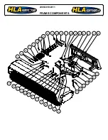
Page 17: ...2009 2010 2011 FRAME COMPONENTS 10 9 8 11 5 22 7 3 16 12 21 3 5 15 3 4 23 24 6 16 14 20 8 9 20 8 13 18 10 11 2 17 4 9 2 19 1 18 4 4 ...

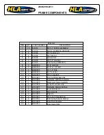
Page 18: ...030 2 10 1 4 Lock Nut LA SB1031 2 11 3 4 x 2 Hex Bolt LA SS1025 4 12 Pivot Subframe Assembly LP 100293 1 13 Oscillation Subframe Assembly LP 100294 1 14 Attachment Frame Assembly LP 100295 1 15 Spring Mount Assembly LP 100296 2 16 Oscillation Retainer Bushing LP 100297 1 17 Angle Cylinder Pin LP 100298 2 18 Main Pivot Pin LP 100299 1 19 Float Pin LP 100300 2 20 5 8 x 16 Threaded Rod LP 100301 3 21...

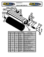
Page 19: ... Weldment LP 100292 1 N A 8 Drive Plate Assembly LP 100304 1 1 9 Motor Mount Bracket LP 100305 1 1 10 Single Castor Wheel Assembly LP 100306 N A 2 11 Motor Shield LP 100307 1 1 12 Caster Top Retainer Washer LP 100308 2 2 13 72 Broom Head Weldment LP 100312 N A 1 14 Single 6 Caster Yoke LP 100980 N A 2 15 Double 6 Castor Yoke LP 100981 2 N A 16 Double Caster Wheel Assembly LP 100982 2 N A 17 4 Bolt...

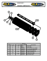
Page 20: ...t Lock Washer LA SB1184 6 6 3 1 2 Helical Spring Lock Washer LA SS1002 6 6 4 84 Broom 50 50 Wafer Set LP 100303 1 N A 5 72 Broom 50 50 Wafer Set LP 100313 N A 1 6 84 Broom Inner Frame LP 100314 1 N A 7 72 Broom Inner Frame LP 100318 N A 1 8 Broom Retainer Plate LP 100322 1 1 9 2009 2010 2011 BROOM COMPONENTS 1 7 8 3 4 2 9 4 3 5 6 ...

Page 21: ...000810 5 4 90 9 16 M JIC 9 16 M ORB HF 68010606 2 5 3 4 16 90 M JIC 7 8 14 M ORB HF 68010810 1 6 Female FF Quick Coupler HF FF150808 1 7 Male FF Quick Coupler HF FM150808 1 8 Supply Hose 1 2 HH100074 2 9 84 Drive Hose 1 2 HH100075 1 10 Angle Cyl Hose 1 4 Rear Port HH100076 1 11 Angle Cyl Hose 1 4 Front Port HH100077 1 12 MLHS 400 Hydraulic Motor HM MLHS400 1 13 Selector Switch Box Wire LP 100311 1...

Page 22: ...6 78 106 121 164 171 232 5 8 15 16 110 149 170 230 240 325 1 1 8 192 261 297 403 420 569 7 8 1 5 16 306 416 474 642 669 907 1 1 1 2 467 634 722 979 1020 1383 Metric Series Torque Chart Diameter Thread Pitch millimeters Wrenc h Size Metric Grade 8 8 Metric Grade 10 9 Metric Grade 8 8 Metric Grade 10 9 Diameter Thread Pitch millimeters Coarse Thread Fine Thread N m lbs ft N m lbs ft N m lbs ft N m l...

Page 23: ...et screw out 1 turns tighten jam nut Dirt or debris in spools Contact your dealer or HLA Brush head assembly bounces during sweeping Travel speed too fast and or brush speed too slow Find correct combination of ground and brush speeds do not travel at more than 5 mph 8 kph Core is bent Replace core Brush wears into cone shape Broom is not level Level Broom before each use Tires on power unit at di...

Page 24: ... oil Hydraulic oil heating Dirty oil Drain and refill oil replace filter Partially plugged inlet filter Clean filter element Oil too light in hot weather Use recommended oil Damaged oil lines Replace oil lines External hydraulic fluid leakage Motor seals damaged Repair motor Broken oil lines Replace hose and check for leaks Loose hydraulic connection Tighten loose connections Hydraulic pump capaci...

Page 25: ...ity for any damages that may result from the use or misuse by his employees or others Distributor dealer must notify Horst Welding of the defect by phone fax or email Recommended repairs and cost are to be discussed with and agreed on by an authorized Horst Welding representative Repair and labor at an agreed rate will be performed by a dealer for Horst Welding or a repair shop designated by Horst...

Reviews: