6 (10)
3.1
Connectors
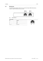
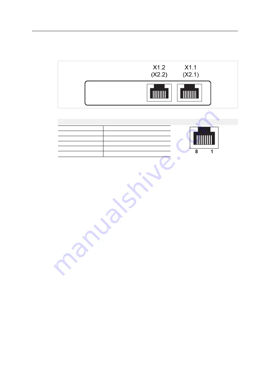
This interface has two RJ45 type Ethernet connectors that are labeled
X1.1
/
X1.2
when top-
mounted, and
X2.1
/
X2.2
when bottom-mounted.
Fig. 2
Network interface
RJ45 pin layout
Pin
Function
1
TD+
2
TD-
3
RD+
6
RD-
4, 5, 7, 8
(reserved)
POWERLINK Slave Anybus
®
X-gateway
™
Network Interface User Manual
SCM-1202-091 1.1 en-US


