background image

Installation

5 (10)

3

Installation

This product contains parts that can be damaged by electrostatic discharge (ESD). Use
ESD prevention measures to avoid damage.

Make sure that you have all the necessary information about the capabilities and restrictions of
your local network environment before installation.

Prerequisites

The following items may be needed for installation:

USB cable (included)

Ethernet cable (not included)

Configuration tool for POWERLINK (optional, not included)

XDD file for POWERLINK (download from

www.anybus.com/support

)

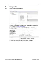
Anybus Configuration Manager (download from

www.anybus.com/support

)

Basic Installation Steps

1.

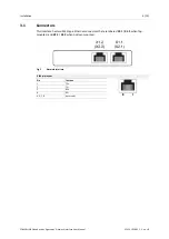
Connect the POWERLINK Slave Interface to the network.

2.

Connect the USB cable between the gateway and the computer to use for configuration.

3.

Connect power and power on the gateway.

4.

Download and install Anybus Configuration Manager

5.

Download and Install the XDD file in the POWERLINK configuration tool.

6.

Configure the gateway as required.

POWERLINK Slave Anybus

®

X-gateway

Network Interface User Manual

SCM-1202-091 1.1 en-US

Summary of Contents for Anybus X-gateway

Page 1: ...POWERLINK Slave Anybus X gateway Network Interface USER MANUAL SCM 1202 091 1 1 en US ENGLISH...

Page 2: ...ents associated with any particular implementation HMS Industrial Networks cannot assume responsibility or liability for actual use based on the data examples or illustrations included in this documen...

Page 3: ...Table of Contents Page 1 Preface 3 1 1 About This Document 3 1 2 Document history 3 1 3 Document Conventions 3 2 Description 4 2 1 Overview 4 2 2 Data Flow 4 3 Installation 5 3 1 Connectors 6 3 2 LED...

Page 4: ...This page intentionally left blank...

Page 5: ...ction leads to this result Bold typeface indicates interactive parts such as connectors and switches on the hardware or menus and buttons in a graphical user interface Monospaced text is used to indic...

Page 6: ...ission of data will never interfere and precise communication timing is guaranteed This mechanism is called Slot Communication Network Management SCNM SCNM is managed by one particular networked devic...

Page 7: ...tion tool for POWERLINK optional not included XDD file for POWERLINK download from www anybus com support Anybus Configuration Manager download from www anybus com support Basic Installation Steps 1 C...

Page 8: ...rnet connectors that are labeled X1 1 X1 2 when top mounted and X2 1 X2 2 when bottom mounted Fig 2 Network interface RJ45 pin layout Pin Function 1 TD 2 TD 3 RD 6 RD 4 5 7 8 reserved POWERLINK Slave...

Page 9: ...n single flash Only asynchronous data Green double flash Asynchronous and synchronous data No PDO data Green triple flash Ready to operate Asynchronous and synchronous data No PDO data Green Operating...

Page 10: ...NK Output PDO Size bytes Input SDO Size bytes Amount of acyclical I O data to exchange on POWERLINK Output SDO Size bytes Offline option Action if the POWERLINK network goes offline Clear reset the da...

Page 11: ...d dynamic mapping Ring redundancy Process Data Objects PDO for I O exchange Service Data Object SDO for explicit messaging 1 TPDO and 1 RPDO are supported Segmented SDO transfer Poll Reponse chaining...

Page 12: ...last page 2019 HMS Industrial Networks Box 4126 300 04 Halmstad Sweden info hms se SCM 1202 091 1 1 en US 2019 04 11 12834...

Reviews: