Configuration 3-6
© 2012 HMS Industrial Networks AB
Doc.Id. HMSI-168-25
Modbus Network Configuration
The Modbus network configuration contains the parameters used to control the
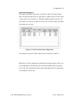
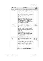
behavior of the Modbus serial interface. The parameters are described in Table 3-
1 below. Refer to Figure 3-1 to see how each parameter is displayed on the user
interface.
Parameter
Description
Allowable
Range
Network Address
The address of the module on the Modbus net-
work. This is the slave address that the master
device will use when sending commands to
the module. All modules on the network must
have a unique address.
1 - 247
Baud Rate
The network baud rate. All devices on the net-
work must use the same baud/parity/stop bits
configuration.
4800
9600
19200
Parity
The serial communication parity configura-
tion. All devices on the network must use the
same baud/parity/stop bits configuration.
None
Even
Odd
Stop Bits
The number of stop bits used in the serial
communication. All devices on the network
must use the same baud/parity/stop bits con-
figuration.
1 or 2
Watchdog
Time-out
The time in milliseconds after receiving a
message from the master before the module
detects that it is no longer connected to a mas-
ter. If a message is not received from the
Modbus master within the configured timeout
period, the module will revert to Idle mode.
(J1939 message transmission is suspended in
Idle mode.) The module will switch to, and
remain in, Run mode when messages are
being received from a master.
0 - 65535
Table 3-1 Modbus Network Configuration Parameters


