background image

6.2. Set Up Wireless Infrastructure

Connect two or more Bolt Serial units via WLAN or Bluetooth using Easy Config.

Procedure

Connecting the Devices

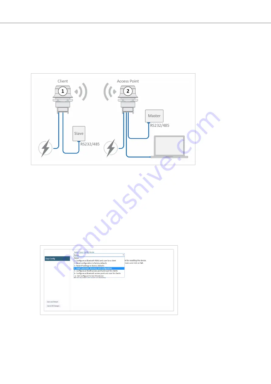
Figure 22. Serial bridge

1.

Connect Client 1 to a Slave serial device. See also 

Connect to LAN, Serial and Power

.

2.

Connect Access Point 2 to the Master device.

3.

Connect Access Point 2 to your PC, with an Ethernet cable.

4.

Connect Access Point 2 to power.

Activate Easy Config

1.

Navigate to the web interface of Access Point 2.
The default address to Access Point unit 2 is 192.168.0.99.

2.

Activate one of the following Easy Config Modes:

Figure 23. Easy Config modes menu

• Easy Config Mode 1 for Bluetooth PANU-PANU. Used for setting up point-to-point communication.
• Easy Config Mode 5 for WLAN.
• Easy Config Mode 6 for Bluetooth.

Anybus

®

 Wireless Bolt Serial

Set Up Wireless Infrastructure

Page 38 of 60

SCM-1202-143 2.0

Summary of Contents for Anybus AWB2010

Page 1: ...Anybus Wireless Bolt Serial USER MANUAL SCM 1202 143 Version 2 0 Publication date 2022 04 07 ENGLISH ...

Page 2: ...t and because of the many variables and requirements associated with any particular implementation HMS Networks cannot assume responsibility or liability for actual use based on the data examples or illustrations included in this document nor for any damages incurred during installation of the product Those responsible for the use of the product must acquire sufficient knowledge in order to ensure...

Page 3: ...tion Methods 15 5 6 Wireless Configuration via Access Point Unit 15 5 7 Configuration with Easy Config 16 5 7 1 Available Easy Config Modes 16 5 7 2 Easy Config Modes Time Considerations 16 5 7 3 How to Activate an Easy Config Mode 17 5 8 Configuration with AT Commands 18 5 8 1 Enable Fast Roaming with AT Commands 19 5 8 2 Digital Input 19 5 8 3 Add Additional WLAN Channels with AT Commands 20 5 9...

Page 4: ...TCP IP Socket Protocol Description 43 7 Verify Operation 44 7 1 Network Connection Status 44 8 Maintenance 45 8 1 Firmware Update 45 8 2 Settings Backup 47 8 2 1 Create Settings Backup File 47 8 2 2 Restore Settings From Backup File 47 9 Troubleshooting 48 9 1 Reset Button 48 9 2 Recovery Mode 49 9 3 Reset to Factory Default 50 10 Technical Data 52 10 1 Technical Specifications 52 11 Reference Gui...

Page 5: ...nd script examples Cross References and Links Cross reference within this document Document Conventions page 1 External link URL www anybus com Safety Symbols DANGER Instructions that must be followed to avoid an imminently hazardous situation which if not avoided will result in death or serious injury WARNING Instructions that must be followed to avoid a potential hazardous situation that if not ...

Page 6: ...r operation TIP Helpful advice and suggestions 1 3 Trademarks Anybus is a registered trademark and Wireless Bolt Serial is a trademark of HMS Networks AB All other trademarks are the property of their respective holders Anybus Wireless Bolt Serial Trademarks Page 2 of 60 SCM 1202 143 2 0 ...

Page 7: ... terminals CAUTION This equipment is recommended for use in both industrial and domestic environments For industrial environments it is mandatory to use the functional earth connection to comply with immunity requirements For domestic environments the functional earth must be used if a shielded Ethernet cable is used in order to meet emission requirements 2 2 Intended Use The intended use of this ...

Page 8: ...l interference a minimum distance of 50 cm between the devices should be observed See Wireless Technology Basics page 55 3 4 When to Use Bluetooth or WLAN Use Bluetooth when The wireless link has an Anybus Wireless Bolt or Anybus Wireless Bridge II at both ends An interruption free connection is more important than data throughput speed Interference robustness is important e g in an industrial env...

Page 9: ... minimum I Odata cycle times for PROFINET and EtherNet IP networks Wireless link Point to Point with Bluetooth PANU PANU or Wi Fi Access Point to Station 32 ms Wireless link with Access Point and up to 4 wireless clients stations Bluetooth or Wi Fi 64 ms I O Data Cycle Time Considerations Anybus Wireless Bolt Serial SCM 1202 143 2 0 Page 5 of 60 ...

Page 10: ...lent to Ra 3 2 or finer and cleaned and free from oils and greases Installation IMPORTANT Make sure that the sealing ring is correctly placed in the circular groove in the top part of the housing before tightening the nut IMPORTANT Always hold the BOTTOM part of the unit when untightening the nut not the top part the cap Tightening torque 5 Nm 10 All measurements are in mm Figure 1 Installation dr...

Page 11: ...refer to RS232 RS485 Electrical Connection page 54 Pin Name Description 1 VIN Power 9 30 V 2 GND Power Ground 3 DI Digital input 9 30 V 4 DI_GND Digital input ground 5 ETN_RD Ethernet receive white orange 6 ETN_RD Ethernet receive orange 7 ETN_TD Ethernet transmit green 8 ETN_TD Ethernet transmit white green 9 RS485_B RS 485 B Line 10 FE Shield Ethernet Functional Earth Serial and CAN Functional E...

Page 12: ...ntwist the twisted pair cable as little as possible Procedure Create connector cable for Bolt Serial 1 Cut off one of the connectors on a standard Cat5e or Cat6 Ethernet cable 2 Strip off about 40 mm 1 inch of the cable jacket and untwist the orange orange white green and green white wires The shield and the other wires are not used 3 Strip off about 7 mm inch of the isolation on each wire 4 Push ...

Page 13: ...4 4 Reset Button Figure 3 Reset button The Reset button is located on the bottom of the Bolt Serial Reset Button Anybus Wireless Bolt Serial SCM 1202 143 2 0 Page 9 of 60 ...

Page 14: ...eb interface is accessed by pointing a web browser to the IP address of the unit The default address is 192 168 0 99 See also Access the Built In Web Interface page 11 Figure 4 System Overview page example The System Overview page shows current settings and network connection status The Help page describes the AT commands that can be used for advanced configuration Anybus Wireless Bolt Serial Conf...

Page 15: ...ange the IP Address on the Bolt Serial Ethernet port Use the software application HMS IPconfig to find and change the IP address on the Bolt Serial Ethernet port to one within the same IP address range as the PC accessing the Bolt Serial built in web interface To download the installation files please visit www anybus com support and enter the product article number to search for the Bolt Serial s...

Page 16: ...rd The default username is admin written in lowercase letters You find the default password on the Bolt Serial product housing NOTE The Bolt Serial default IP address is 192 168 0 99 Procedure Login to the Bolt Serial built in web interface 1 Open a web browser 2 Click to select the Address bar and enter the Bolt Serial IP address Figure 5 Enter IP address in web browser 3 Press Enter The built in...

Page 17: ...e made to the settings In the left sidebar menu click Cancel All Changes To restore settings see Restore Settings From Backup File page 47 Apply Changes To apply changes click Save and Reboot in the left sidebar menu Bolt Serial restarts for the changes to take effect To Save and Reboot Anybus Wireless Bolt Serial SCM 1202 143 2 0 Page 13 of 60 ...

Page 18: ...l Bands 2 4 GHz 5 GHz Authentication Mode WPA WPA2 PSK Channel Auto Bridge Mode Layer 3 IP forward Default Bluetooth Settings Operating Mode PANU Client Local Name generated from MAC address Connectable No Discoverable No Security Mode Just works Default Serial Settings Operating Mode RS232 Baud Rate 57600 bits s Data bits 8 Stop bits 1 Parity No parity Modbus optimization Off TCP Mode Server Modb...

Page 19: ... the web interface or over a Telnet or RAW TCP connection to port 8080 For more information about how to use the AT commands navigate to the built in web interface Help page or see the AT Commands Reference Guide See also Configuration with AT Commands page 18 5 6 Wireless Configuration via Access Point Unit Configuration of Wireless Bolt and Bridge Clients can be performed wirelessly via a PC con...

Page 20: ...factory defaults 3 N A Reset IP settings to factory defaults 4 Client Configure units in mode 4 as Clients Wait for automatic configuration The unit listens for 120 seconds or until receiving a configuration When mode 4 is used with mode 1 5 or 6 Serial Settings TCP Mode Client is activated automatically 5 WLAN AP The unit scans for other units in Config Mode 4 and configure them as Clients Timeou...

Page 21: ...y Config menu 1 In the built in web interface navigate to the Easy Config page 2 To activate an Easy Config mode select it from the drop down menu and click Set See also Available Easy Config Modes page 16 The selected mode is activated immediately Configuration with Easy Config Anybus Wireless Bolt Serial SCM 1202 143 2 0 Page 17 of 60 ...

Page 22: ...n be used to read out parameters in text format and for batch configuration using command scripts For a complete list of supported AT commands click Help in the built in web interface See also the AT Commands Reference Guide at www anybus com support Procedure Figure 9 AT Commands and AT Results 1 Enter or paste the AT commands into the Enter AT Command s text field 2 Click Send 3 The result codes...

Page 23: ...Serial Send the Reboot device AT Command AT AMREBOOT For more information about how to set up WLAN roaming see the AT Commands Reference Guide or the Help page in the built in web interface 5 8 2 Digital Input The digital input can be used to control roaming between Bluetooth access points NAP For more information refer to the AT Commands Reference Guide at www anybus com support IMPORTANT If volt...

Page 24: ...he unit will revert to World Mode The unit must then be restarted to update the regulatory domain For more information about how to use AT commands see the AT Commands Reference Guide or the Help page in the web interface For information on possible channels to include see WLAN Channels and World Mode page 26 Procedure Enable or Disable World Mode and add WLAN channels 1 To Enable or Disable World...

Page 25: ...3 For the change to take effect reboot the Bolt Serial Send the Reboot device AT Command AT AMREBOOT Configuration with AT Commands Anybus Wireless Bolt Serial SCM 1202 143 2 0 Page 21 of 60 ...

Page 26: ...on is only available when IP Assignment is set to Static To avoid IP address conflict if a DHCP server is already active on the network use the DHCP Interfaces setting to limit the internal DHCP server to the correct interface DHCP Interfaces The DHCP Interfaces function is available when Internal DHCP Server DHCP Server Enabled is selected All By default the DHCP Interfaces function is set to use...

Page 27: ...Controller the connectivity may be reduced The cause may be Multiple devices sharing a single wireless interface is not typically supported without special configuration The network cannot enforce a 1 to 1 mapping of IP to MAC addresses and must allow propagation of broadcasted ARP messages over the wireless segment in order to route traffic to the bridged devices If this for security or performan...

Page 28: ... Access Point is selected additional settings will be available Channel Bands NOTE The unit can be configured to scan on both the 2 4 GHz and 5 GHz channel bands but can only communicate on one band at a time Choose to scan only the 2 4 GHz or 5 GHz channel band or both default Anybus Wireless Bolt Serial Configure Settings in the Built In Web Interface Page 24 of 60 SCM 1202 143 2 0 ...

Page 29: ... Select the authentication encryption mode required by the network When Open is selected there is no encryption or authentication Passkey When using WPA WPA2 PSK or WEP64 128 enter the passkey Username Domain Passphrase Authentication details when using LEAP or PEAP WPA2 Enterprise 5 9 5 WLAN Roaming Bolt Serial supports Fast Roaming according to IEEE 802 11r This enables a WLAN Client to roam qui...

Page 30: ...ation The unit is initially set in World Mode which enables only the universally allowed channels in the 2 4 GHz and 5 GHz bands Table 3 Regulatory domains and WLAN channels Domain 2 4 GHz 5 GHz WORLD 1 11 36 40 44 48 52 56 60 64 100 104 108 112 116 132 136 140 ETSI 1 11 12 13 36 40 44 48 52 56 60 64 100 104 108 112 116 120 124 128 132 136 140 149 153 157 161 165 FCC 1 11 36 40 44 48 52 56 60 64 1...

Page 31: ...etween 8 and 63 characters All characters in the ASCII printable range 32 126 are allowed except double quote comma and backslash Hexadecimal passwords must start with 0x and be exactly 64 characters See WPA2 Password Examples page 27 Channel Bands Channel Select the WLAN channel band and channel to use for the Access Point Valid channels are 1 to 11 for the 2 4 GHz band and 36 40 44 48 for the 5 ...

Page 32: ... cloned MAC only Layer 2 data from only a single MAC address specified below will be bridged over WLAN many to one Layer 3 IP forward Default setting IP data from all devices will be bridged over WLAN This mode must be used when using the DHCP Relay function See Layer 3 IP Forward Connectivity Considerations page 23 Cloned MAC Address The MAC address to use with Layer 2 cloned MAC only Cloned IP A...

Page 33: ...ding the last 6 characters of the MAC ID Connectable Enable to make the unit accept connections initiated by other Bluetooth devices Discoverable Enable to make the unit visible to other Bluetooth devices Connect to settings Setting Description Security Mode Disabled No encryption or authentication PIN Encrypted connection with PIN code security This mode only works between two units of this type ...

Page 34: ...ted Connect To Used when connecting manually to a NAP or PANU device Connection Scheme Choose whether to select a Bluetooth device by MAC address default or Name when connecting manually Connecting to MAC will lock the connection to a specific hardware while connecting to Name allows for more flexibility MAC Name MAC address or Name of the Bluetooth device to connect to Anybus Wireless Bolt Serial...

Page 35: ... data will be bridged over Bluetooth This mode must be used when connecting to an Android device over Bluetooth The network must have an active DHCP server List Nearby Devices Scans the network and lists discoverable Bluetooth devices Pairing cannot be initiated in NAP mode Configure Settings in the Built In Web Interface Anybus Wireless Bolt Serial SCM 1202 143 2 0 Page 31 of 60 ...

Page 36: ... Settings example TCP Mode Server with Modbus TCP to Modbus RTU Gateway function enabled Figure 18 Serial Settings page TCP Mode Server Anybus Wireless Bolt Serial Configure Settings in the Built In Web Interface Page 32 of 60 SCM 1202 143 2 0 ...

Page 37: ...ive data 7 micro seconds after the last bit is sent Data Bits Specify the number of data bits to transmit Select 5 6 7 or 8 bits To transmit binary data select 8 data bits Parity Specify if parity should be used to detect code errors No parity No parity checking parity bit is not transmitted Odd parity The parity bit is asserted or unasserted to obtain an odd number of mark bits Even Even parity c...

Page 38: ... is active enter the TCP Port number Default port 5005 When Modbus Gateway Mode is active the port automatically changes to Modbus TCP port 502 Show Statistics Select Show Statistics to view Serial Rx and Tx statistics Buffer Size The bytes in the queue handled with in the order they were received Used Part of the buffer used Total Total size of the buffer Dropped The number of dropped data packet...

Page 39: ... multipoint link A message sent from a master to a Bolt Serial is forwarded to all the connected slaves The slave response sent to the Bolt Serial is forwarded to the master but not to the other slaves Example 6 Point to multipoint link Message sent from Master and response sent from Slaves Configure Settings in the Built In Web Interface Anybus Wireless Bolt Serial SCM 1202 143 2 0 Page 35 of 60 ...

Page 40: ... file on your computer Restore Settings Click Choose file and select a previously saved configuration then click Load The settings in the saved configuration will be applied and the unit will reboot General Configuration Setting Description Reboot System Reboots the system without applying changes Cancel All Changes Restores all parameters in the web interface to the currently active values Factor...

Page 41: ...ion Serial cable replacement is enabled by using two pieces of Bolt Serial which creates a wireless bridge for the Serial communication Figure 21 Bolt Serial Point to Point Installation Use Cases Anybus Wireless Bolt Serial SCM 1202 143 2 0 Page 37 of 60 ...

Page 42: ...2 to your PC with an Ethernet cable 4 Connect Access Point 2 to power Activate Easy Config 1 Navigate to the web interface of Access Point 2 The default address to Access Point unit 2 is 192 168 0 99 2 Activate one of the following Easy Config Modes Figure 23 Easy Config modes menu Easy Config Mode 1 for Bluetooth PANU PANU Used for setting up point to point communication Easy Config Mode 5 for WL...

Page 43: ...nt 1 is disconnected from Ethernet Disconnect Client 1 from power and repeat the steps to activate Easy Config Add Additional Bolt Serial Clients Option when using Easy Config Mode 1 Continue with the configuration see Serial Configuration page 40 Option when using Easy Config Mode 5 or 6 You can add up to 6 additional Bolt Serial Clients to the serial bridge To add additional Clients Figure 24 Se...

Page 44: ...re the serial port settings see Set Up Serial Communication page 32 6 3 Installing Multiple Bolt Serial Units Figure 26 Installing Multiple Bolt Serial When installing more than one Bolt Serial in the network infrastructure configure the unit connected to the Master device as the Access Point AP Slave as a Client Anybus Wireless Bolt Serial Installing Multiple Bolt Serial Units Page 40 of 60 SCM 1...

Page 45: ...Bolt Serial connected to the Master device as the Wireless Access point AP Slave as a Wireless Client Modbus Optimization In the Bolt Serial Access Point built in web interface Serial Settings page select the Modbus Optimization checkbox Installing on a Modbus Network Anybus Wireless Bolt Serial SCM 1202 143 2 0 Page 41 of 60 ...

Page 46: ...e Access Point AP or Network Access Point NAP Connect the Modbus RTU Slaves The Modbus RTU Slaves are all Modbus Servers One of the Modbus RTU Slaves is connected to Bolt Serial B with IP address 192 168 0 100 The other Modbus RTU Slaves are connected to Bolt Serial C with IP address 192 168 0 101 Modbus TCP Client Configuration Configure the Modbus TCP Client to access the correct Modbus Slave Sl...

Page 47: ...ss to the devices over the network Set up TCP IP communication 1 Establish IP connectivity between the devices using either WLAN or Bluetooth PAN profile 2 Do one of the following Open a TCP IP socket towards the Bolt Serial Use the configured TCP port number default 5005 Up to 7 active sockets are supported simultaneously Configure the Bolt Serial as a TCP Client to connect to a specific IP Resul...

Page 48: ... 1 Network Connection Status The System Overview page shows current settings and network connection status Figure 30 System Overview page example Anybus Wireless Bolt Serial Verify Operation Page 44 of 60 SCM 1202 143 2 0 ...

Page 49: ...rial to your computer refer to Connecting to PC and Power Procedure Update the Bolt Serial firmware Figure 31 Firmware Update Choose file 1 Click Choose File 2 In the Open dialog box browse to and select the firmware update file and click Open 3 To start the file transfer click Send NOTE Do not refresh or leave the Firmware Update page until the process has finished Maintenance Anybus Wireless Bol...

Page 50: ...nsfer is finished the progress bar turns green Reboot Figure 33 Firmware Update Waiting for reboot When the firmware update is finished Bolt Serial automatically reboots for the updates to take effect The progress bar Waiting for reboot indicates the progress When the reboot is complete the web browser automatically redirects to the System Overview page Anybus Wireless Bolt Serial Firmware Update ...

Page 51: ...m Backup File IMPORTANT When you restore settings from a backup file all the current settings are overwritten by the settings loaded from the backup file Figure 35 Restore Settings from a backup file Restore settings from a backup file 1 Click Choose file 2 Browse to and select your backup file 3 Click Load The Bolt Serial reboot automatically for the settings loaded from the backup file to take e...

Page 52: ...9 Troubleshooting 9 1 Reset Button Figure 36 Reset button The Reset button is located on the bottom of the Bolt Serial Anybus Wireless Bolt Serial Troubleshooting Page 48 of 60 SCM 1202 143 2 0 ...

Page 53: ...gh the built in web interface Procedure To enter Recovery Mode 1 Press and hold MODE button during startup Figure 37 RESET button 2 Bolt Serial enters Recovery Mode To Reinstall the Firmware 1 To reinstalling the firmware you need Anybus Firmware Manager II Download Anybus Firmware Manager II from www anybus com support 2 Install Anybus Firmware Manager II on your PC 3 Launch Anybus Firmware Manag...

Page 54: ...Using the RESET Button Press and hold RESET for 10 seconds and then release it Reset Via the Built In Web Interface Launch the built in web interface On the System Settings page click Factory Restore Reset Using Easy Config To reset Bolt Serial to factory default execute Easy Config Mode 2 See Activate an Easy Config Mode in the Built In Web Interface page 17 Anybus Wireless Bolt Serial Reset to F...

Page 55: ... and then restart the unit See Configuration with AT Commands page 18 Reset Using Digital Input To reset Bolt Serial to factory default apply voltage to the digital input for 10 seconds See Connector page 7 Reset to Factory Default Anybus Wireless Bolt Serial SCM 1202 143 2 0 Page 51 of 60 ...

Page 56: ...cording to IEC 60068 2 6 2007 and with extra severities Number of axes 3 mutually perpendicular X Y Z Duration 10 sweep cycles in each axes Velocity 1 oct min Mode in operation Frequency 5 500 Hz Displacement 3 5 mm Acceleration 2g Shock test according to IEC 60068 2 27 2008 and with extra severities Wave shape half sine Number of shocks 3 in each axes Mode In operation Axes X Y Z Acceleration 30 ...

Page 57: ...onsumption 36 mA 24VDC Net data throughput 1 Mbps Bluetooth version support Classic Bluetooth v2 1 Security Authentication Authorization Encryption Data Protection Privacy Confidentiality NIST Compliant FIPS Approved Technical Specifications Anybus Wireless Bolt Serial SCM 1202 143 2 0 Page 53 of 60 ...

Page 58: ... or D and B is TX RX or D RS232 Typical Connection Figure 38 RS232 Typical Connection RS485 Typical Connection NOTE The resistors on the Bolt Serial side are termination resistors which form an active termination of the RS485 line Figure 39 RS485 Typical Connection Anybus Wireless Bolt Serial Reference Guides Page 54 of 60 SCM 1202 143 2 0 ...

Page 59: ...es and on the signal wave length As a rule of thumb at least 60 of the first innermost Fresnel zone must be free of obstacles to maintain good reception Figure 40 Fresnel zones Area to keep clear of obstacles first Fresnel zone Distance d Fresnel zone radius r 2 4 GHz WLAN or Bluetooth 5 GHz WLAN 100 m 1 7 m 1 2 m 200 m 2 5 m 1 7 m 300 m 3 0 m 2 1 m 400 m 3 5 m 2 4 m The wireless signal may be ade...

Page 60: ...iew This diagram shows the horizontal antenna pattern when looking at the Bolt from above i e looking at the top logo from above Figure 41 Bolt top view Diagram Analysis NOTE Limited gain for 5 GHz between 105 to 190 The diagram displays an omnidirectional antenna gain regarding 2 4 GHz blue line which is used for Bluetooth and Wireless LAN 2 4 GHz It also shows that Wireless LAN 5 GHz orange line...

Page 61: ...elow the Bolt Figure 43 Antenna pattern Boltrotation 0 and 90 Diagram Analysis The vertical antenna gain is fairly omnidirectional for both frequencies It is also clear to see that the metal cabinet where the Bolt is mounted will increase the gain upwards in reference to the surface where the Bolt is mounted Thus the gain downwards is limited as expected Radio Antenna Patterns Anybus Wireless Bolt...

Page 62: ...uge difference between using a back shield to focus the radio energy and not using a back shield Using a back shield can greatly increase radio coverage if used correctly The diagram covers both the Anybus Wireless Bolt and the Anybus Wireless Bridge when using Wi Fi WLAN 2 4 GHz Anybus Wireless Bolt Serial Radio Antenna Patterns Page 58 of 60 SCM 1202 143 2 0 ...

Page 63: ...Figure 46 Radio Antenna Patterns Anybus Wireless Bolt Serial SCM 1202 143 2 0 Page 59 of 60 ...

Page 64: ...This page is intentionally left blank ...

Reviews: