


6.5. Installing Using the Modbus TCP to RTU Gateway Function
The gateway function is transparent. When a command is sent on Modbus TCP it is translated to Modbus RTU.
The response is translated back to Modbus TCP and delivered to the Modbus TCP Client.
It is possible to connect Bolt Serial to a pre-existing wireless infrastructure, such as the wireless network in a
production facility.
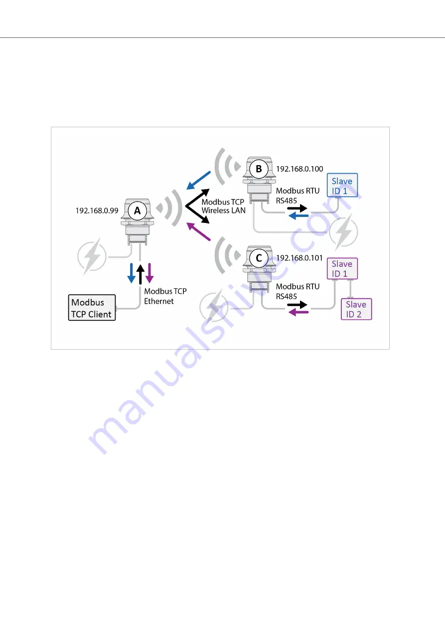
Figure 28. Serial bridge, Modbus RTU to RTU Gateway function
Bolt Serial Access Point Unit
• Configure Bolt Serial A, with IP address 192.168.0.99, connected to the Modbus TCP Client as the Access Point
(AP) or Network Access Point (NAP).
Connect the Modbus RTU Slaves
The Modbus RTU Slaves are all Modbus Servers.
• One of the Modbus RTU Slaves is connected to Bolt Serial B with IP address 192.168.0.100.
• The other Modbus RTU Slaves are connected to Bolt Serial C with IP address 192.168.0.101.
Modbus TCP Client Configuration
Configure the Modbus TCP Client to access the correct Modbus Slave:
• Slave ID 1 connected to Bolt Serial B:
IP address 192.168.0.100 and unit identifier 1.
• Slave ID 1 connected to Bolt Serial C:
IP address 192.168.0.101 and unit identifier 1.
• Slave ID 2 connected to Bolt Serial C:
IP address 192.168.0.101 and unit identifier 2.
Anybus
®
Wireless Bolt Serial
™
Installing Using the Modbus TCP to RTU Gateway Function
Page 42 of 60
SCM-1202-143 2.0


