


11.3. Radio Antenna Patterns
This section presents information about the radio antenna patterns for the Anybus Wireless Bolt.
The diagram scale shows relative RSSI values, where the outer ring represents maximum radio power and is
labelled 0 dB.
The inner rings represent the increasing attenuation in dB measured in different angles around the Bolt, while
maintaining the same distance.
Azimuth (Horizontal) View
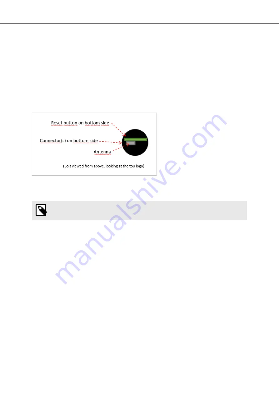
This diagram shows the horizontal antenna pattern when looking at the Bolt from above, i.e. looking at the top
logo from above.
Figure 41. Bolt top view
Diagram Analysis
NOTE
Limited gain for 5 GHz between 105° to 190°.
The diagram displays an omnidirectional antenna gain regarding 2.4 GHz (blue line) which is used for Bluetooth
and Wireless LAN 2.4 GHz.
It also shows that Wireless LAN 5 GHz (orange line) has a limited antenna gain in the approximate directions 105°
to 190°, i.e. the 5 GHz range will be limited in this direction.
Anybus
®
Wireless Bolt Serial
™
Radio Antenna Patterns
Page 56 of 60
SCM-1202-143 2.0


