30
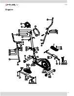
H0103
54
52 38
53 8 34
54
33
22
8
34
7
27
16
37
38
54
53
8
34
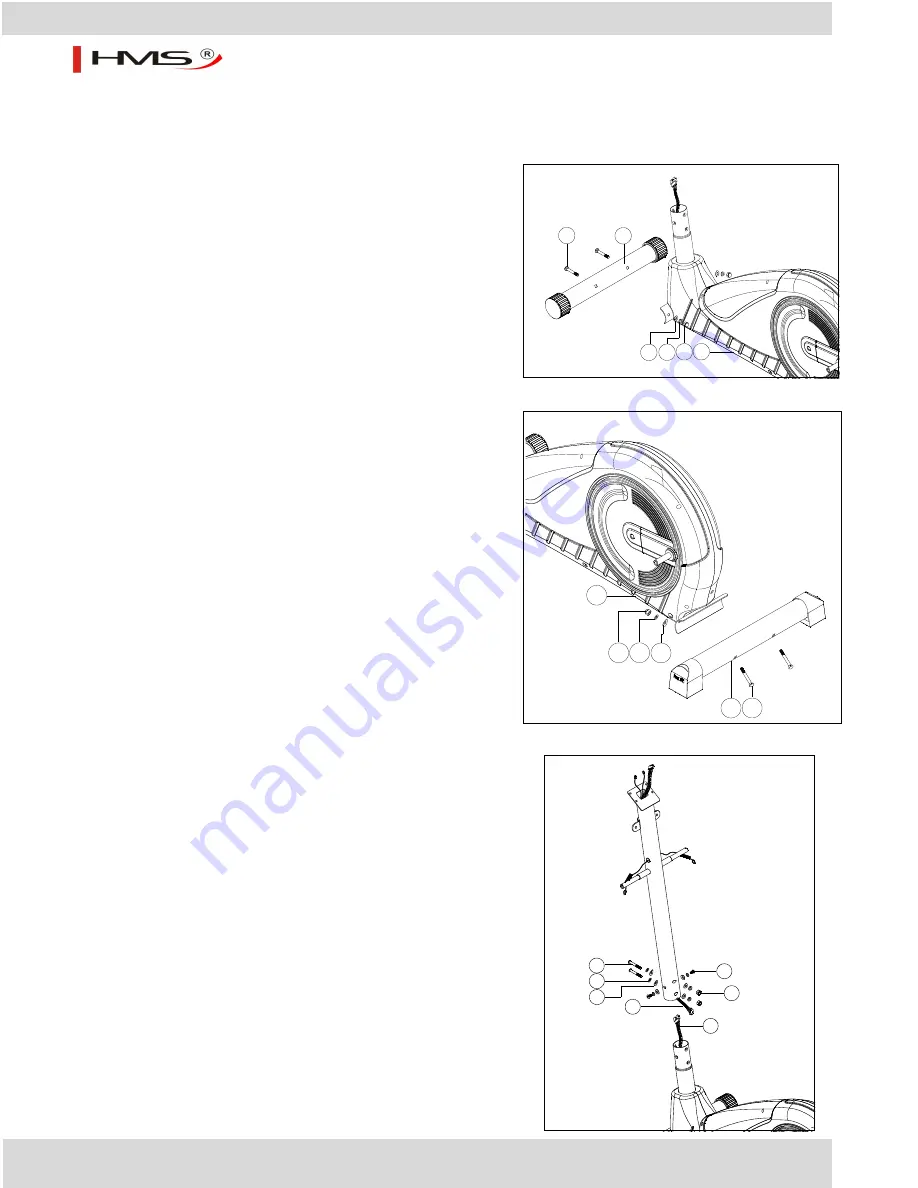
Assembly instruction
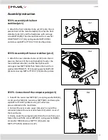
STEP 1.Assembly of the front
stabilizer(pic 1)
1. Attach the front stabilizer tube set (37) onto the arc
piecein front of the main frame(54).Transfer the front
stabilizer tube (37) and the fixed piece with carriage
screw M8*74(38). Then fasten them with arc washer
OD20*ID8.5*1.5T (34), spring washer M8*2.0T(8)
and screw cap M8*1.25*15.5T (53) like the picture.
STEP 2.Assembly of the rear stabilizer (pic 2)
1. Attach the rear stabilizer tube set (52) onto the arc
piece on the back of the main frame(54).Transfer the
rear stabilizer tube (52) and the fixed piece with
carriage screw M8*74(38).Then fasten them with arc
washer OD20*ID8.5*1.5T (34),spring washer M8*2.0T
(8) and screw cap M8*1.25*15.5T (53) like the picture
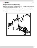
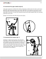
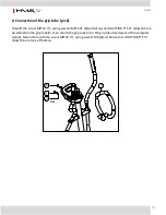
STEP 3. Connection of the computer pole (pic 3)
1. Take off the two screw M8*20(7), six spring washer M8 (8),
six Arc washer M8 (34), two screw M8*70(22) and two nylon
cap M8*1.25*6.35T (subtence 13) (27) which are
pre-assembled on the mainframe.
2. Connect the sensor wire upper (16) which is out of the
computer pole to the sensor wire lower (33) which is out of
the main frame.
3. Finally, cover the computer pole (9) to the main frame set,
fasten them with the screw M8*20(7), spring washer M8(8),
arc washer M8 (34),screw M8*70 (22),nylon cap
M8*1.25*6.35T(subtence 13) (27).
Pic.2
Pic.3
Pic.1
Summary of Contents for H0103
Page 59: ...59 H0103 Podrobn n kres...


