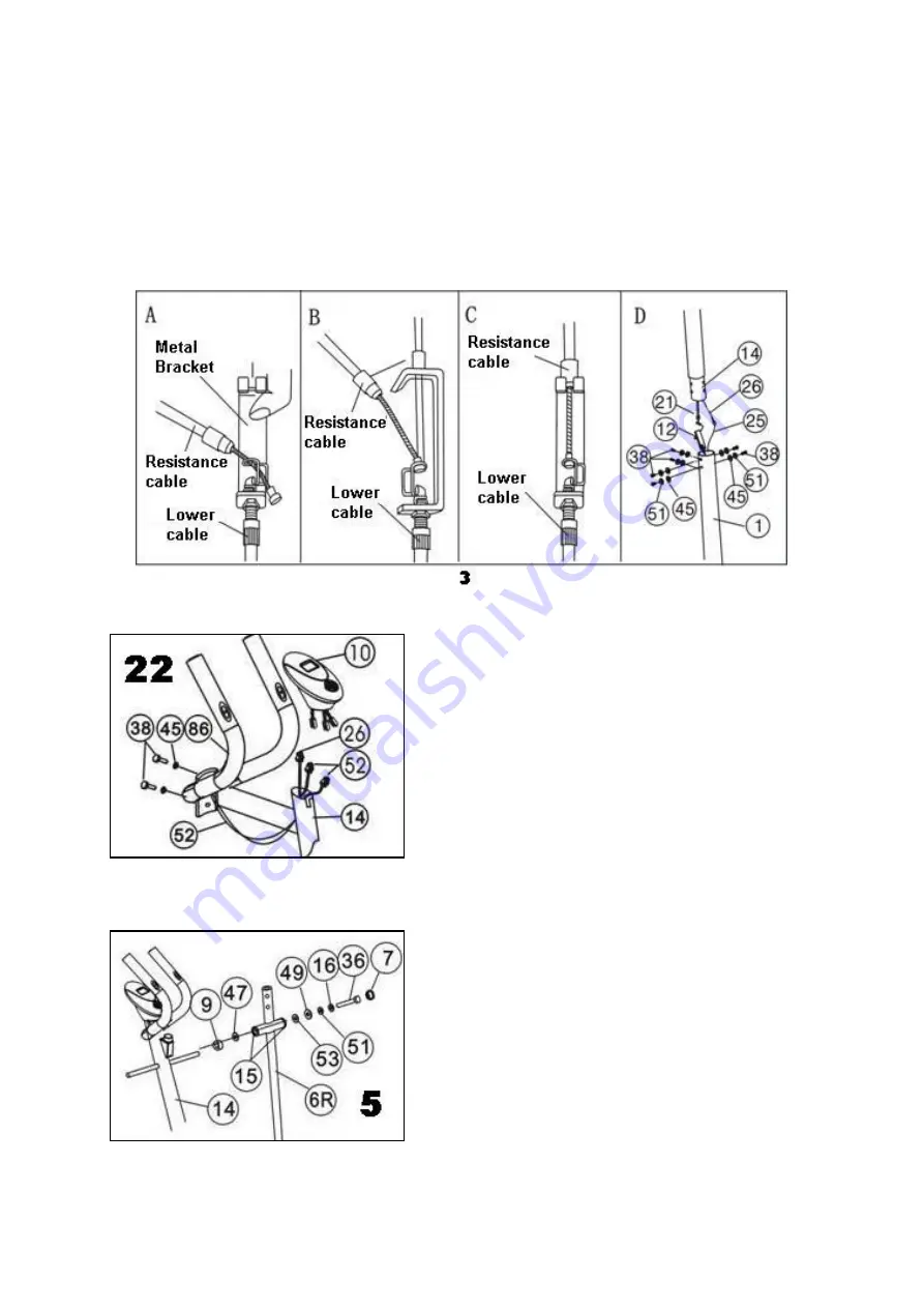
3. Install the Front Upright Frame
Put the end of resistance cable into the spring hook of Tension control wire (12) as shown on
drawing
A
of figure 3. Pull the resistance cable up and force it into the gap of metal bracket
of Tension control wire (12) as shown on drawing
B
of figure3. Connect the resistance cable
with the Tension control wire (12) completed as shown on drawing
C
of figure 3. Connect the
computer wire (26) to the Sensor wire (25) coming out from mainframe (1). Insert the Front
upright frame (14) to the main frame (1) and secure it with six pcs of Bolts (38), Spring
washers (51), and Arc washers (45) as shown on drawing
D
of figure 3.
4. Install the hand pulse tube and Computer
a.
Insert the Pulse wires (52) to the holes on the
back of the Front upright frame (14), and pull
them out from the top of the Front upright frame.
Attach the hand pulse tube (86) on the admire
holes on the Front upright frame(14) with 2pcs
of M8X16 bolts (38), Arch washers(45). (Refer
picture 4)
b.
Insert the Pulse wires (52) and Computer wire
(26) to the holes on the back of the Computer
(10).
c.
Attach the Computer (10) to the top of the Front
upright frame (14). (Refer figures 4)
5. Install the Handlebar Support (Right & Left)
a. Attach one Arc spacers
(9) and Ø16 Wave
washer (47) to the right end of horizontal axis of
Front upright frame (14).
b. Insert right Handlebar support (6R) to the right
end of horizontal axis of Front upright frame (14)
and secure it with one Plastic flat washer (53),
Ø8 Big washer (49), spring washer (51), Special
washer (16), and M8X16 Bolt (36).
c. Assemble the Nut cap (7) to M8X16 Bolt (36),
and then the right Handlebar support (6R) can
move freely.
d. Do the same steps as the above to assemble the left Handlebar support (6L) to the left
end of horizontal axis of Front upright frame (14). (Refer figure 5)


