Intesis
TM
Modbus Server
– Mitsubishi Electric CC
User Manual r1.1 EN
© HMS Industrial Networks S.L.U - All rights reserved
This information is subject to change without notice
URL
http
s
://www.intesis.com
13 / 25
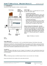
Power device
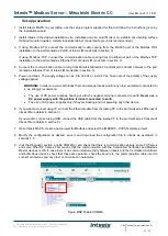
The first step to perform is to power up the device. To do so, a power supply working with any of the voltage range
allowed is needed (check section 5). Once connected the ON led will turn on.
Connect to
Mitsubishi’s Centralized Controller(s).
Connect the communication cable coming from the network hub, switch or direct from the Centralized Controller to
the Ethernet port (Figure 3.1) of the gateway. The cable to be used shall be a straight Ethernet UTP/FTP CAT5 cable.
In case there is no response from Mitsubishi Centralized Controller to the frames sent by the gateway, check that it
is operative and reachable from the network connection used by the gateway. Check the gateway
’s Ethernet interface
sending Pings to its IP address using a PC connected to the same Ethernet IP network. If the problem persists
communicating through the LAN of the building, contact the network administrator and make sure traffic on the port
used is allowed through all the LAN path.
Intesis Modbus Server
– Mitsubishi Centralized Controller
comes with DHCP functionality enabled by default.
Connection to Modbus
3.1.1 Modbus TCP
Same ethernet connection as for Mitsubishi’s Centralized Controller is used. Connect the communication cable
coming from the network hub or switch to the Ethernet port of Intesis. The cable to be used shall be a straight Ethernet
UTP/FTP CAT5 cable.
3.1.2 Modbus RTU
Connect the communication cable coming from the Modbus network to the port marked as Port B of Intesis. Connect
the EIA485 bus to connectors B1 (-
), B2 (+) and B3 (SNGD) of gateway’s PortB. Respect the polarity.
Remember the characteristics of the standard EIA485 bus: maximum distance of 1200 meters, maximum 32 devices
(without repeaters) connected to the
bus, and in each end of the bus it must be a termination resistor of 120 Ω. The
gateway has an internal bus biasing circuit that incorporates the termination resistor.
Bus biasing and termination
resistor for EIA485 can be enabled for PortB by means of a dedicated DIP switch.
Connect to PC (Configuration tool)
This action allows the user to have access to configuration and monitoring of the device. Two methods to connect to
the PC can be used:
•
Ethernet
: Using the Ethernet port of the Intesis.
•
USB cable
: To connect the device to the PC, the USB cable supplied should be plugged to the USB Console
port.

